JeepParts
My Garage
My Account
Cart
OEM 2004 Chrysler Sebring Axle Shaft
Car Axle Shaft- Select Vehicle by Model
- Select Vehicle by VIN
Select Vehicle by Model
orMake
Model
Year
Select Vehicle by VIN
For the most accurate results, select vehicle by your VIN (Vehicle Identification Number).
19 Axle Shafts found


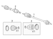
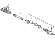
2004 Chrysler Sebring Inner Shaft, Front Part Number: MR276837
Product Specifications- Other Name: Shaft - Front Axle; CV Intermediate Shaft, Front; Shaft; Shaft Front Axle
- Position: Front
- Item Weight: 5.70 Pounds
- Item Dimensions: 15.3 x 12.7 x 3.1 inches
- Condition: New
- Fitment Type: Direct Replacement
- SKU: MR276837
- Warranty: This genuine part is guaranteed by Mopar's factory warranty.

 Product Specifications
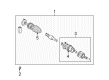
- Other Name: Shaft - Axle Half; CV Axle Assembly, Front Right; Shaft Axle Half
- Position: Front Passenger Side
- Replaces: RL017653AA, 4593448AB, 4593448AA, RX017653AA
- Item Weight: 22.20 Pounds
- Item Dimensions: 44.3 x 5.0 x 5.0 inches
- Condition: New
- Fitment Type: Direct Replacement
- SKU: 5017653AA
- Warranty: This genuine part is guaranteed by Mopar's factory warranty.

 Product Specifications
- Other Name: Shaft - Axle Half; CV Axle Assembly, Front Right; Constant Velocity Axle; Axle Shaft; Shaft Axle Half; CV Axle Assembly
- Position: Front Passenger Side
- Replaces: RX593388AB
- Item Weight: 19.50 Pounds
- Item Dimensions: 43.1 x 4.9 x 4.8 inches
- Condition: New
- Fitment Type: Direct Replacement
- SKU: 4593388AB
- Warranty: This genuine part is guaranteed by Mopar's factory warranty.
- Product Specifications
- Other Name: Shaft - Axle Half; CV Axle Assembly, Front Left; Shaft Axle Half
- Position: Front Driver Side
- Replaces: RX017654AA, 4593449AA
- Item Weight: 16.30 Pounds
- Item Dimensions: 4.7 x 4.9 x 31.2 inches
- Condition: New
- Fitment Type: Direct Replacement
- SKU: 5017654AA
- Warranty: This genuine part is guaranteed by Mopar's factory warranty.

 Product Specifications
- Other Name: Shaft - Front Axle; CV Axle Assembly, Front Right; Constant Velocity Axle; Axle Shaft; Shaft Front Axle; CV Axle Assembly
- Position: Front Passenger Side
- Condition: New
- Fitment Type: Direct Replacement
- SKU: MR410044
- Warranty: This genuine part is guaranteed by Mopar's factory warranty.
- Product Specifications
- Other Name: Shaft - Front Axle; CV Axle Assembly, Front Left; Shaft Front Axle
- Position: Front Driver Side
- Condition: New
- Fitment Type: Direct Replacement
- SKU: MR410043
- Warranty: This genuine part is guaranteed by Mopar's factory warranty.
- Product Specifications
- Other Name: Shaft - Front Axle; CV Axle Assembly, Front Left; Constant Velocity Axle; Axle Shaft; Shaft Front Axle; CV Axle Assembly
- Position: Front Driver Side
- Condition: New
- Fitment Type: Direct Replacement
- SKU: MR357811
- Warranty: This genuine part is guaranteed by Mopar's factory warranty.
- Product Specifications
- Other Name: Shaft - Front Axle; CV Axle Assembly, Front Right; Constant Velocity Axle; Axle Shaft; Shaft Front Axle; CV Axle Assembly
- Position: Front Passenger Side
- Condition: New
- Fitment Type: Direct Replacement
- SKU: MR196740
- Warranty: This genuine part is guaranteed by Mopar's factory warranty.
- Product Specifications
- Other Name: Shaft - Front Axle; CV Axle Assembly, Front Right; Constant Velocity Axle; Axle Shaft; Shaft Front Axle; CV Axle Assembly
- Position: Front Passenger Side
- Condition: New
- Fitment Type: Direct Replacement
- SKU: MR410042
- Warranty: This genuine part is guaranteed by Mopar's factory warranty.
- Product Specifications
- Other Name: Shaft - Front Axle; CV Axle Assembly, Front Left; Shaft Front Axle
- Position: Front Driver Side
- Condition: New
- Fitment Type: Direct Replacement
- SKU: MR410041
- Warranty: This genuine part is guaranteed by Mopar's factory warranty.
 Product Specifications
- Other Name: Shaft - Front Axle; CV Axle Assembly, Front Left; Shaft Front Axle
- Position: Front Driver Side
- Item Weight: 15.70 Pounds
- Condition: New
- Fitment Type: Direct Replacement
- SKU: MR357815
- Warranty: This genuine part is guaranteed by Mopar's factory warranty.
- Product Specifications
- Other Name: Shaft - Front Axle; CV Axle Assembly, Front Left; Constant Velocity Axle; Axle Shaft; Shaft Front Axle; CV Axle Assembly
- Position: Front Driver Side
- Item Weight: 15.30 Pounds
- Condition: New
- Fitment Type: Direct Replacement
- SKU: MR357813
- Warranty: This genuine part is guaranteed by Mopar's factory warranty.
- Product Specifications
- Other Name: Shaft - Front Axle; CV Axle Assembly, Front Left; Constant Velocity Axle; Axle Shaft; Shaft Front Axle; CV Axle Assembly
- Position: Front Driver Side
- Item Weight: 13.80 Pounds
- Condition: New
- Fitment Type: Direct Replacement
- SKU: MR357809
- Warranty: This genuine part is guaranteed by Mopar's factory warranty.
2004 Chrysler Sebring Inner Shaft, Front Part Number: MR357370
Product Specifications- Other Name: Shaft - Front Axle; CV Intermediate Shaft, Front; Axle Shaft; Shaft; Shaft Front Axle
- Position: Front
- Condition: New
- Fitment Type: Direct Replacement
- SKU: MR357370
- Warranty: This genuine part is guaranteed by Mopar's factory warranty.
- Product Specifications
- Other Name: Shaft - Front Axle; CV Axle Assembly, Front Right; Shaft Front Axle
- Position: Front Passenger Side
- Item Weight: 15.60 Pounds
- Condition: New
- Fitment Type: Direct Replacement
- SKU: MR196766
- Warranty: This genuine part is guaranteed by Mopar's factory warranty.
- Product Specifications
- Other Name: Shaft - Front Axle; CV Axle Assembly, Front Right; Constant Velocity Axle; Axle Shaft; Shaft Front Axle; CV Axle Assembly
- Position: Front Passenger Side
- Item Weight: 15.20 Pounds
- Condition: New
- Fitment Type: Direct Replacement
- SKU: MR196764
- Warranty: This genuine part is guaranteed by Mopar's factory warranty.
- Product Specifications
- Other Name: Shaft - Front Axle; CV Axle Assembly, Front Right; Constant Velocity Axle; Axle Shaft; Shaft Front Axle; CV Axle Assembly
- Position: Front Passenger Side
- Item Weight: 18.00 Pounds
- Condition: New
- Fitment Type: Direct Replacement
- SKU: MR196738
- Warranty: This genuine part is guaranteed by Mopar's factory warranty.
 Product Specifications
- Other Name: Shaft - Axle Half; CV Axle Assembly, Front Left; Constant Velocity Axle; Axle Shaft; Shaft Axle Half; CV Axle Assembly
- Position: Front Driver Side
- Condition: New
- Fitment Type: Direct Replacement
- SKU: 4578023AA
- Warranty: This genuine part is guaranteed by Mopar's factory warranty.
- Product Specifications
- Other Name: Shaft - Axle Half; CV Axle Assembly, Front Right; Constant Velocity Axle; Axle Shaft; Shaft Axle Half; CV Axle Assembly
- Position: Front Passenger Side
- Condition: New
- Fitment Type: Direct Replacement
- SKU: 4578022AA
- Warranty: This genuine part is guaranteed by Mopar's factory warranty.
2004 Chrysler Sebring Axle Shaft Parts and Q&A
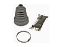
- Q: How to Remove and Install an Axle Shaft on 2004 Chrysler Sebring?A: Before removing the half shaft, hoist the vehicle and remove the wheel and tire of the front tire. Next, remove the bolts holding the caliper adapter to the knuckle and lift out the complete caliper/adapter assembly using mechanic's wire, so it doesn't press the hose. Remove the brake rotor and the nut connecting the tie rod to the steering knuckle, then clamp an 11/32 socket onto the end of the tie rod stud to loosen and remove that nut. With Tool MB-991113, disconnect the tie rod end from the steering knuckle arm and take out the halfshaft-to-hub and bearing retaining nut. With no tool under the lower ball joint, remove the cotter pin and castle nut from the smaller ball joint stud at the steering knuckle. Turn the steering knuckle outward and hit it with a hammer at the knuckle boss, making sure not to hurt the control arm or grease seal while separating the knuckle from the ball joint stud. Don't take apart the inner ON joint and stabilize the driveshaft throughout the procedure. Release the halfshaft from the steering knuckle and if it won't budge, insert Puller 1026 to guide the shaft out of the hub/bearing housing. Pry between the inner tripod connection and transaxle case to remove the halfshaft while doing no harm to the oil seal and support the outer end of the shaft assembly. Work against the tripod joint by pushing it down to unseat the snap ring from the transaxle and then hold the inner tripod and shaft while lifting it out from the transaxle. During installation, first clean the spline and oil seal surfaces of the tripod joint, then lubricate them with new transmission lubricant and set the tripod joint into the transaxle side gear by hand. Twist the tripod's lever firmly until the snap ring is engaged and can't be removed by you. Before putting the halfshaft back into the front hub, remove all debris from the area around the front part of the outer C/V joint where it will fit. The castle nut should be tightened to 95 Nm (70 ft. lbs.) after putting the knuckle onto the lower control arm ball stud. Insert the tie rod end into the steering knuckle and tighten the nut with a crowfoot and 11/32 socket to 55 Nm (41 ft. lbs.). After that, fit the brake rotor onto the hub. Place the assembly on the steering knuckle, tighten the caliper adapter bolts to 88 Nm (65 ft. lbs.). Remove all debris from the CN joint, install the hub nut onto the halfshaft and tighten the nut to 150 Nm (110 ft.lbs.) after applying the brakes. After that, fit the front wheel and tire assembly and tighten the lug nuts so they reach 135 Nm (100 ft. lbs.) in the correct sequence.