JeepParts
My Garage
My Account
Cart
OEM 2006 Chrysler 300 ABS Control Module
Anti Lock Brake Control Module- Select Vehicle by Model
- Select Vehicle by VIN
Select Vehicle by Model
orMake
Model
Year
Select Vehicle by VIN
For the most accurate results, select vehicle by your VIN (Vehicle Identification Number).
7 ABS Control Modules found


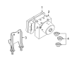
2006 Chrysler 300 Control Module Part Number: 5175609AE
Product Specifications- Other Name: Module - Anti-Lock Brake System; ABS Control Module
- Replaces: 5175609AA, 5175609AC, 5175609AD, 5175609AB
- Item Weight: 2.40 Pounds
- Item Dimensions: 7.3 x 6.8 x 6.4 inches
- Condition: New
- Fitment Type: Direct Replacement
- SKU: 5175609AE
- Warranty: This genuine part is guaranteed by Mopar's factory warranty.


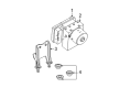
2006 Chrysler 300 Modulator Part Number: 68004546AA
Product Specifications- Other Name: Master Cylinder - Anti-Lock Brake System; ABS Modulator Valve; ABS Control Module; Hydraulic Control Unit Anti-Lock Brake System
- Replaces: 5175605AA
- Item Weight: 5.10 Pounds
- Item Dimensions: 7.4 x 6.0 x 5.7 inches
- Condition: New
- Fitment Type: Direct Replacement
- SKU: 68004546AA
- Warranty: This genuine part is guaranteed by Mopar's factory warranty.


2006 Chrysler 300 Control Module Part Number: 5191296AA
Product Specifications- Other Name: Module - Anti-Lock Brake System; ABS Modulator Valve; ABS Control Module; Modulator; Module Anti-Lock Brake System
- Replaces: 5159193AA
- Item Weight: 2.10 Pounds
- Item Dimensions: 7.1 x 6.9 x 6.3 inches
- Condition: New
- Fitment Type: Direct Replacement
- SKU: 5191296AA
- Warranty: This genuine part is guaranteed by Mopar's factory warranty.

2006 Chrysler 300 Control Module Part Number: 5159192AC
Product Specifications- Other Name: Module - Anti-Lock Brake System; ABS Modulator Valve; ABS Control Module; Modulator; Module Anti-Lock Brake System
- Item Weight: 2.20 Pounds
- Condition: New
- Fitment Type: Direct Replacement
- SKU: 5159192AC
- Warranty: This genuine part is guaranteed by Mopar's factory warranty.


2006 Chrysler 300 Control Module Part Number: 5134111AA
Product Specifications- Other Name: Master Cylinder - Anti-Lock Brake System; ABS Modulator Valve; ABS Control Module; Modulator Valve; Modulator; Hydraulic Control Unit Anti-Lock Brake System
- Item Weight: 6.00 Pounds
- Condition: New
- Fitment Type: Direct Replacement
- SKU: 5134111AA
- Warranty: This genuine part is guaranteed by Mopar's factory warranty.
2006 Chrysler 300 Control Module Part Number: 5136134AC
Product Specifications- Other Name: Module - Anti-Lock Brake System; ABS Control Module; Module Anti-Lock Brake System
- Item Weight: 2.10 Pounds
- Item Dimensions: 7.1 x 7.1 x 6.6 inches
- Condition: New
- Fitment Type: Direct Replacement
- SKU: 5136134AC
- Warranty: This genuine part is guaranteed by Mopar's factory warranty.
2006 Chrysler 300 Control Module Part Number: 5134113AA
Product Specifications- Other Name: Master Cylinder - Anti-Lock Brake System; ABS Modulator Valve; ABS Control Module; Modulator Valve; Modulator; Hydraulic Control Unit Anti-Lock Brake System
- Item Weight: 7.30 Pounds
- Item Dimensions: 6.9 x 7.2 x 6.6 inches
- Condition: New
- Fitment Type: Direct Replacement
- SKU: 5134113AA
- Warranty: This genuine part is guaranteed by Mopar's factory warranty.
2006 Chrysler 300 ABS Control Module Parts and Q&A
- Q: How to Service and Repair an ABS Control Module on 2006 Chrysler 300?A: Begin by removing the negative battery cable from the battery post and placing it away to work on the module. Following that, separate the wires at the Antilock Brake Module. Remove the brake tubes from the two upper radiator support clips and also from the clip below the Fuse And Relay Center. Lift both calipers with their brackets from the mounting grommets and move them closer so you can unscrew the ABM screws without squeezing the brake tubes. Take out the three screws that connect the ABM to the Hydraulic Control Unit and slide it off. To install, match the ABM solenoids and pump/motor cord to the HCU valves and connecting passage and press the ABM onto the HCU. Screw the ABM in place to the HCU so the screws overlap with each other, then tighten each one to 2 N.m of force. Fit the assembly on top of the mounting grommets and snap the mounting bracket into its place. Fit the brake tube under the Fuse And Relay Center to the routing clip and attach the other brake tubes to the clips at the upper radiator support. Connect the 47-way wiring connector at the ABM and reattach the negative battery cable to its post in the correct way. Do the Diagnostic Verification Test and fix any problems that come up.
Related 2006 Chrysler 300 Parts
 2006 Chrysler 300 Brake Caliper
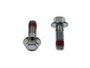 2006 Chrysler 300 Brake Caliper Bolt
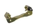 2006 Chrysler 300 Brake Caliper Bracket
 2006 Chrysler 300 Brake Caliper Piston
 2006 Chrysler 300 Brake Disc
 2006 Chrysler 300 Brake Dust Shield
 2006 Chrysler 300 Brake Line
 2006 Chrysler 300 Brake Pad
 2006 Chrysler 300 Hydraulic Hose
 2006 Chrysler 300 Parking Brake Shoe
 2006 Chrysler 300 Wheel Bearing Dust Cap
 2006 Chrysler 300 Wheel Stud