JeepParts
My Garage
My Account
Cart
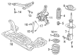
OEM 2004 Dodge Neon Control Arm
Suspension Arm- Select Vehicle by Model
- Select Vehicle by VIN
Select Vehicle by Model
orMake
Model
Year
Select Vehicle by VIN
For the most accurate results, select vehicle by your VIN (Vehicle Identification Number).
4 Control Arms found


2004 Dodge Neon Control Arm, Front Lower Driver Side Part Number: 4656731AN
$246.42 MSRP: $376.00You Save: $129.58 (35%)Ships in 1-2 Business DaysProduct Specifications- Other Name: Arm - Lower Control; Front Left Suspension Control Arm and Ball Joint Assembly.; Lower Control Arm; Arm Lower Control Front; Arm Control; Suspension Control Arm
- Position: Front Lower Driver Side
- Replaces: 4656731AL, 4656731AH, 4656731AJ, 4656731AF, 4656731AK, 4656731AM, 4656731AG
- Item Weight: 9.10 Pounds
- Item Dimensions: 3.4 x 14.8 x 17.2 inches
- Condition: New
- Fitment Type: Direct Replacement
- SKU: 4656731AN
- Warranty: This genuine part is guaranteed by Mopar's factory warranty.


2004 Dodge Neon Control Arm, Front Lower Passenger Side Part Number: 4656730AN
$131.39 MSRP: $195.00You Save: $63.61 (33%)Ships in 1-3 Business DaysProduct Specifications- Other Name: Arm - Lower Control; Front Right Suspension Control Arm and Ball Joint Assembly.; Lower Control Arm; Arm Lower Control Front; Arm Control; Suspension Control Arm
- Position: Front Lower Passenger Side
- Replaces: 4656730AK, 4656730AL, 4656730AH, 4656730AM, 4656730AJ, 4656730AG, 4656730AF
- Item Weight: 8.90 Pounds
- Item Dimensions: 3.4 x 14.5 x 16.5 inches
- Condition: New
- Fitment Type: Direct Replacement
- SKU: 4656730AN
- Warranty: This genuine part is guaranteed by Mopar's factory warranty.
2004 Dodge Neon Control Arm, Front Passenger Side Part Number: 5272236AM
$231.05 MSRP: $421.00You Save: $189.95 (46%)Ships in 1-2 Business DaysProduct Specifications- Other Name: Arm - Control; Front Right Suspension Control Arm and Ball Joint Assembly.; Lower Control Arm
- Position: Front Passenger Side
- Replaces: 5272236AF, 5272236AJ, 5272236AL, 5272236AH, 5272236AK, 5272236AC
- Item Weight: 8.50 Pounds
- Item Dimensions: 21.0 x 10.8 x 3.3 inches
- Condition: New
- Fitment Type: Direct Replacement
- SKU: 5272236AM
- Warranty: This genuine part is guaranteed by Mopar's factory warranty.
2004 Dodge Neon Control Arm, Front Driver Side Part Number: 5272237AM
$214.61 MSRP: $347.00You Save: $132.39 (39%)Ships in 1-2 Business DaysProduct Specifications- Other Name: Arm - Control; Suspension Control Arm, Front Left; Lower Control Arm
- Position: Front Driver Side
- Replaces: 5272237AF, 5272237AC, 5272237AK, 5272237AL, 5272237AJ, 5272237AH
- Item Weight: 8.50 Pounds
- Item Dimensions: 21.6 x 11.1 x 3.3 inches
- Condition: New
- Fitment Type: Direct Replacement
- SKU: 5272237AM
- Warranty: This genuine part is guaranteed by Mopar's factory warranty.
2004 Dodge Neon Control Arm Parts and Q&A
- Q: How to Install the Control Arm and Its Related Components on 2004 Dodge Neon?A: The first step is to put the lower control arm into the front suspension crossmember. Hold off on fully tightening the rear bolt attaching the lower control arm and frame rail, as well as the front bolt, before tucking the blown engine away. Without loading the lower control arm, tighten the rear bolt to 185 ft lbs and the front bolt to 125 ft lbs. Then, place the ball joint stud into the knuckle with the bolt hole fitting the notch and use a new pinch bolt and nut to tighten to 95 Nm (70 ft lbs). When servicing the appropriate lower control arm, add the engine torque strut. Place a washer on the main strut's upstanding bolt, slip the pencil strut onto the corner of the crossmember and vehicle ahead of the wheel and tighten the nut to a torque of 52 Nm (38 ft lbs). After that, place the drive-belt splash shield and fasten it to the body and front suspension crossmember and install any front fascia fasteners you removed. Attach the wheel house splash shield to the drive belt splash shield as well. Place the front ends of the stabilizer bar in position, clean the threads in the stabilizer bar link bolts and use Lock and Seal from Mopar or a similar product. Install one assembly on each side and while doing so, bolt the lower bushing onto the bottom of the stabilizer bar, move it through the inner link's bushing, down into the lower arm's bushing and end with the upper retainer/nut and bushing. Place the tire and wheel assembly, drop the vehicle and when required, position it on a platform hoist or alignment track to reach the stabilizer bar mounting bolts at curb height. At curb level, turn the link bolt inside each stabilizer bar while holding the upper retainer/nut with a wrench and reaching a tightening value of 29 Nm (22 ft lbs). Then, with the stabilizer bar loose again, secure the bolts till they reach 25 Nm (18 ft lbs) with a torque wrench and ensure wheel alignment when required.
Related 2004 Dodge Neon Parts
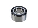 2004 Dodge Neon Wheel Bearing
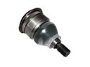 2004 Dodge Neon Ball Joint
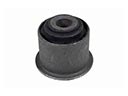 2004 Dodge Neon Axle Pivot Bushing
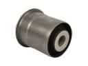 2004 Dodge Neon Axle Support Bushings
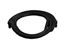 2004 Dodge Neon Coil Spring Insulator
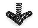 2004 Dodge Neon Coil Springs
 2004 Dodge Neon Lateral Link
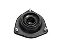 2004 Dodge Neon Shock And Strut Mount
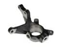 2004 Dodge Neon Steering Knuckle
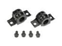 2004 Dodge Neon Sway Bar Bracket
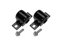 2004 Dodge Neon Sway Bar Bushing
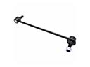 2004 Dodge Neon Sway Bar Link