JeepParts
My Garage
My Account
Cart
OEM 2005 Dodge Magnum Control Arm
Suspension Arm- Select Vehicle by Model
- Select Vehicle by VIN
Select Vehicle by Model
orMake
Model
Year
Select Vehicle by VIN
For the most accurate results, select vehicle by your VIN (Vehicle Identification Number).
7 Control Arms found


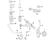
2005 Dodge Magnum Lower Control Arm, Front Upper Passenger Side Part Number: 4895668AB
$417.93 MSRP: $615.00You Save: $197.07 (33%)Ships in 1-2 Business DaysProduct Specifications- Other Name: Arm - Upper Control; Front Right Suspension Control Arm and Ball Joint Assembly.; Upper Control Arm; Arm Upper Control Front; Suspension Control Arm; Control Arm
- Position: Front Upper Passenger Side
- Replaces: 5180596AB, 4895668AA, 5180596AC
- Item Weight: 5.80 Pounds
- Item Dimensions: 12.4 x 12.9 x 4.0 inches
- Condition: New
- Fitment Type: Direct Replacement
- SKU: 4895668AB
- Warranty: This genuine part is guaranteed by Mopar's factory warranty.


2005 Dodge Magnum Lower Control Arm, Front Upper Driver Side Part Number: 4895669AB
$417.93 MSRP: $615.00You Save: $197.07 (33%)Ships in 1-2 Business DaysProduct Specifications- Other Name: Arm - Upper Control; Front Left Suspension Control Arm and Ball Joint Assembly.; Upper Control Arm; Arm Upper Control Front; Suspension Control Arm; Control Arm
- Position: Front Upper Driver Side
- Replaces: 5180597AA, 5180597AB, 5180597AC, 4895669AA
- Item Weight: 5.80 Pounds
- Item Dimensions: 12.4 x 9.7 x 3.9 inches
- Condition: New
- Fitment Type: Direct Replacement
- SKU: 4895669AB
- Warranty: This genuine part is guaranteed by Mopar's factory warranty.


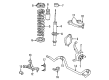
2005 Dodge Magnum Upper Control Arm, Front Driver Side, Steel Part Number: 4782665AB
$149.56 MSRP: $221.00You Save: $71.44 (33%)Product Specifications- Other Name: Arm - Control; Front Left Upper Suspension Control Arm and Ball Joint Assembly.; Arm Control; Suspension Control Arm; Control Arm
- Position: Front Upper Driver Side
- Item Weight: 5.80 Pounds
- Material: Steel
- Item Dimensions: 13.6 x 12.5 x 3.1 inches
- Condition: New
- Fitment Type: Direct Replacement
- SKU: 4782665AB
- Warranty: This genuine part is guaranteed by Mopar's factory warranty.

2005 Dodge Magnum Upper Control Arm, Front Passenger Side, Steel Part Number: 4782666AB
$149.56 MSRP: $221.00You Save: $71.44 (33%)Product Specifications- Other Name: Arm - Control; Front Right Upper Suspension Control Arm and Ball Joint Assembly.; Arm Control; Suspension Control Arm; Control Arm
- Position: Front Upper Passenger Side
- Item Weight: 2.40 Pounds
- Material: Steel
- Item Dimensions: 20.2 x 15.8 x 15.3 inches
- Condition: New
- Fitment Type: Direct Replacement
- SKU: 4782666AB
- Warranty: This genuine part is guaranteed by Mopar's factory warranty.

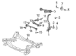
2005 Dodge Magnum Lower Control Arm, Front Part Number: 4782561AE
$243.60 MSRP: $361.00You Save: $117.40 (33%)Product Specifications- Other Name: Arm - Lower Control; Suspension Control Arm, Front Lower Rearward; Suspension Control Arm Bushing; Arm Lower Control Front; Arm Control Lower; Arm Control; Suspension Control Arm; Control Arm
- Position: Front Lower
- Replaces: 4782561AB, 4782561AC, 4782561AF, 4782561AD
- Item Weight: 6.40 Pounds
- Item Dimensions: 3.1 x 4.2 x 16.8 inches
- Condition: New
- Fitment Type: Direct Replacement
- SKU: 4782561AE
- Warranty: This genuine part is guaranteed by Mopar's factory warranty.
 Product Specifications
- Other Name: Arm - Lower Control; Front Left Suspension Control Arm and Ball Joint Assembly.
- Position: Front Lower Driver Side
- Replaces: 4895041AC
- Item Weight: 16.50 Pounds
- Item Dimensions: 18.2 x 15.6 x 6.8 inches
- Condition: New
- Fitment Type: Direct Replacement
- SKU: 4895041AF
- Warranty: This genuine part is guaranteed by Mopar's factory warranty.
- Product Specifications
- Other Name: Arm - Lower Control; Front Right Suspension Control Arm and Ball Joint Assembly.
- Position: Front Lower Passenger Side
- Replaces: 4895040AC
- Item Weight: 17.90 Pounds
- Item Dimensions: 6.7 x 16.0 x 18.7 inches
- Condition: New
- Fitment Type: Direct Replacement
- SKU: 4895040AF
- Warranty: This genuine part is guaranteed by Mopar's factory warranty.
2005 Dodge Magnum Control Arm Parts and Q&A
- Q: How to Remove and Install the Upper Control Arm on 2005 Dodge Magnum?A: If removing the left arm, reposition the coolant recovery container; if taking out the right arm, unbolt the IPM from its mount. Should your kit contain one, unscrew the top cap of the shock tower from the front shock assembly. Cancel the three nuts found underneath the shock assembly on the shock tower, after that the two castle nuts from the upper arm mounting. Elevate and maintain the vehicle, then remove the nuts from the axle mounts and the tire with the wheel. Take off the rubber clip that holds the wheel speed sensor cable to the brake tube bracket. Tighten the nut on the upper ball joint stud until it is level with the end of the stud, then use Puller, Special Tool 9360, along with the ball joint stud, to help you remove it from the knuckle. Lift the upper shock from its base by taking out the ball joint nut and drawing the shock down as you move it sideways so you can get to the mounting bolts. When working on the upper control arm, unlink the headlamp leveling sensor from the arm. Unbolt the top of the control arm from the bracket and pull the control arm out of the shock tower. Slide the upper control arm into the bracket which attaches to the shock tower and install the upper control arm bolts, so the flags on their heads point to the outside. Following service to the right upper control arm, reattach the link from the headlamp leveling sensor. Guide the shock assembly so the studs fit through the holes at the top of the knuckle and attach them to the upper ball joint hole. After that, set the nut on top, tighten it with a hex wrench and reach 47 Nm plus 90° rotation on the knuckle with a crow bar on the torque wrench. Insert the wheel speed sensor cable bracket into the brake tube bracket, fit the tire and wheel assembly into place and secure the wheel mounting nuts to 150 Nm. Drop the vehicle to curb level and tighten the nuts on the upper control arm body mounting bolts to 75 Nm. After that, connect the suspension and tighten the shock tower screws to 27 Nm, attach the shock tower cap to the suspect nuts and snap it on and install the coolant recovery container or the IPM as required.
Related 2005 Dodge Magnum Parts
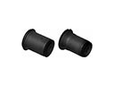 2005 Dodge Magnum Control Arm Bushing
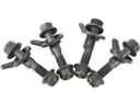 2005 Dodge Magnum Alignment Bolt
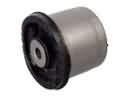 2005 Dodge Magnum Axle Beam Mount
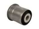 2005 Dodge Magnum Axle Support Bushings
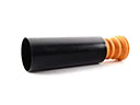 2005 Dodge Magnum Bump Stop
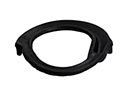 2005 Dodge Magnum Coil Spring Insulator
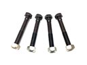 2005 Dodge Magnum Control Arm Bolt
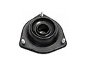 2005 Dodge Magnum Shock And Strut Mount
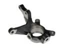 2005 Dodge Magnum Steering Knuckle
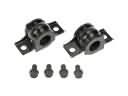 2005 Dodge Magnum Sway Bar Bracket
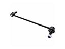 2005 Dodge Magnum Sway Bar Link
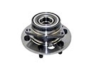 2005 Dodge Magnum Wheel Hub