JeepParts
My Garage
My Account
Cart
OEM 2005 Jeep Grand Cherokee Intake Manifold
Engine Intake Manifold- Select Vehicle by Model
- Select Vehicle by VIN
Select Vehicle by Model
orMake
Model
Year
Select Vehicle by VIN
For the most accurate results, select vehicle by your VIN (Vehicle Identification Number).
3 Intake Manifolds found


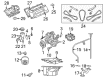
2005 Jeep Grand Cherokee Intake Manifold Part Number: 53032795AC
Product Specifications- Other Name: Manifold - Intake; Engine Intake Manifold
- Replaces: 53032803AB, 53032803AA, 53032795AB, 53032795AA, 53032803AC
- Item Weight: 12.00 Pounds
- Item Dimensions: 12.7 x 16.3 x 20.0 inches
- Condition: New
- Fitment Type: Direct Replacement
- SKU: 53032795AC
- Warranty: This genuine part is guaranteed by Mopar's factory warranty.


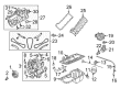
2005 Jeep Grand Cherokee Intake Manifold Part Number: 53032774AA
Product Specifications- Other Name: Manifold - Intake; Engine Intake Manifold; Manifold Intake Includes 1, 3, 4, 5, 6, 12; Manifold Intake
- Item Weight: 13.40 Pounds
- Item Dimensions: 22.2 x 15.1 x 13.8 inches
- Condition: New
- Fitment Type: Direct Replacement
- SKU: 53032774AA
- Warranty: This genuine part is guaranteed by Mopar's factory warranty.

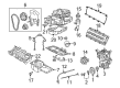
2005 Jeep Grand Cherokee Intake Manifold Part Number: 4591846AJ
Product Specifications- Other Name: Manifold - Intake; Engine Intake Manifold
- Replaces: 4591846AE, 4591846AG, 4591846AH, 4591846AF, 4591846AI
- Item Weight: 25.60 Pounds
- Item Dimensions: 25.3 x 25.7 x 9.8 inches
- Condition: New
- Fitment Type: Direct Replacement
- SKU: 4591846AJ
- Warranty: This genuine part is guaranteed by Mopar's factory warranty.
2005 Jeep Grand Cherokee Intake Manifold Parts and Q&A
- Q: How to Service and Repair an Intake Manifold on 2005 Jeep Grand Cherokee?A: Before you begin to service or repair the intake manifold, first use the Fuel System Pressure Release procedure and remove the negative cable from the battery. Take out the resonator assembly and air inlet hose and then separate the throttle and speed control cables. Disconnect the wires at the connections for the MAP Sensor, IAT Sensor, TPS Sensor, CTS Sensor and IAC Motor. Then, take off the vapor purge hose, brake booster hose, speed control servo hose and Positive Crankcase Ventilation (PCV) hose. Remove the generator and the air conditioning compressor and detach the straps holding the radio suppressors and remove the ignition coil towers from the left and right. After that, eliminate the top tube of the oil dipstick, unplug the ground strap and remove the complete fuel rail and throttle body system with its installing support. Below the coolant steaming point, remove the coolant from the cooling system. Then take out the heater hoses from the front of the engine and heater core, unclip and remove the hoses and tubes from the intake manifold. Fit the engine support fixture (1) with a special tool, # 8534 and remove the right side bolt connecting the frame to the engine mount. After you bring the engine down, set the engine mount in the frame mount, then remove the intake manifold by taking out the fasteners in the order you tightened them. Place the intake manifold gaskets first and after that, install the intake manifold. Place the intake manifold bolts and tighten them to the correct specified amount in the order shown in the picture. After that, put on the left and right radio suppressor straps and finish with the throttle body assembly. After the throttle and speed control cables are connected to the throttle body, you should add the fuel rail and install the ignition coil towers. Put and fix the heater hoses on top of the intake manifold and link them to the heater core and the front cover of the engine. Attach all the connectors again for the MAP Sensor, IAT Sensor, TPS Sensor, CTS Sensor, IAC Motor, ignition coil towers and fuel injectors. Attach the retaining bolt at the top oil dipstick tube and the ground strap and then bolt the generator and air conditioning compressor back in. Installed the vapor purge hose, the brake booster hose, the speed control servo hose and the PCV hose and filled the cooling system, then raised the engine using engine support fixture # 1, with special tool number 8534. Put on the right engine mount bolt (3), remove the engine support fixture and special tool # 8534, then attach the resonator assembly and snake the air inlet hose and lastly, link the negative battery cable.
Related 2005 Jeep Grand Cherokee Parts
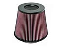 2005 Jeep Grand Cherokee Air Filter
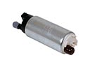 2005 Jeep Grand Cherokee Fuel Pump
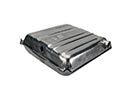 2005 Jeep Grand Cherokee Fuel Tank
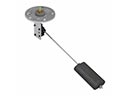 2005 Jeep Grand Cherokee Fuel Sending Unit
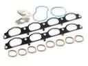 2005 Jeep Grand Cherokee Intake Manifold Gasket
 2005 Jeep Grand Cherokee Air Duct
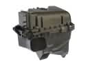 2005 Jeep Grand Cherokee Air Filter Box
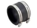 2005 Jeep Grand Cherokee Air Intake Coupling
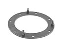 2005 Jeep Grand Cherokee Fuel Pump Gasket
 2005 Jeep Grand Cherokee Fuel Pump Seal
 2005 Jeep Grand Cherokee Fuel Tank Lock Ring
 2005 Jeep Grand Cherokee Throttle Body Gasket