JeepParts
My Garage
My Account
Cart
OEM 2006 Chrysler Sebring Piston
Engine Pistons- Select Vehicle by Model
- Select Vehicle by VIN
Select Vehicle by Model
orMake
Model
Year
Select Vehicle by VIN
For the most accurate results, select vehicle by your VIN (Vehicle Identification Number).
2 Pistons found


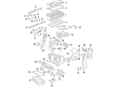
2006 Chrysler Sebring Vibration Damper Part Number: 5142303AB
$56.55 MSRP: $81.25You Save: $24.70 (31%)Ships in 1-3 Business DaysProduct Specifications- Other Name: Piston; Piston Pin And Rod
- Replaces: 5142303AA, 5066565AB
- Item Weight: 3.00 Pounds
- Item Dimensions: 5.7 x 4.4 x 12.6 inches
- Condition: New
- Fitment Type: Direct Replacement
- SKU: 5142303AB
- Warranty: This genuine part is guaranteed by Mopar's factory warranty.

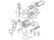
2006 Chrysler Sebring Piston Part Number: 5018627AD
$316.65 MSRP: $576.00You Save: $259.35 (46%)Ships in 1-2 Business DaysProduct Specifications- Other Name: Piston Pin And Rod; Piston Pin And Rod
- Replaces: 5018627AB, 5018627AA, 5018627AC
- Item Weight: 2.60 Pounds
- Item Dimensions: 13.3 x 5.2 x 4.4 inches
- Condition: New
- Fitment Type: Direct Replacement
- SKU: 5018627AD
- Warranty: This genuine part is guaranteed by Mopar's factory warranty.
2006 Chrysler Sebring Piston Parts and Q&A
- Q: How to Install and Remove a Piston in an Engine on 2006 Chrysler Sebring?A: Remove the Balance Shaft Carrier Assembly, oil pan and cylinder head before digging out the piston and connecting rod. Make sure the pistons are covered as you use a reliable ridge reamer to round the top of the cylinder bores. Pistons include a directional stamping on the first half that is visible when facing the front of the engine. Rotate the crankshaft to center every connecting rod in the cylinder bore and replace the pistons and connecting rods into the holes. Label every connecting rod cap with the matching cylinder number by drawing with a permanent ink or paint marker, rather than using a stamp or punch mechanism. Never reuse the connecting rod bolts and ensure you don't damage the surfaces where the fracture rod and cap attach while taking them off. To preserve the crankshaft journal and broken rod surfaces, place Special Tool 8189 and insert the connecting rod guides. After that, use caution while pushing each piston and rod assembly out of the bore opening. Take the guides out and then secure the bearing cap onto the mating rod. Follow these steps for all the pistons and their connecting rods. Before putting in the piston rings, ensure the differences between each ring's gaps prevent them from aligning with the oil ring rail gap. The oil ring expander must be butted and the rail gaps must be set before using the ring compressor. Place both the piston head and rings into engine oil and use the compressor to put in place the piston rings. The front of the engine, as measured from the road, should have the directional stamp on the piston. Turn the crankshaft until the connecting rod journal lines up in the middle of the cylinder and sprinkle engine oil on it. Once the original end of the connecting rod and upper bearing are in place, screw Special Tool 8189 and the connecting rod guides in. Then, tap the piston and help it through the cylinder with the guide in place while the connecting rod takes its position too. After removing the guides, apply some clean engine oil to the new bolts' threads. Put the bottom bearing onto the connecting rod cap and fasten the cap with each bolt finger tight. Then, alternately tighten the bolts to 27 Nm, then tighten an additional 1/4 of a turn without a torque wrench. Use a feeler gauge to inspect clearance on the connecting rods and when done, set in place the Balance Shaft Carrier Assembly, oil pan and cylinder head.
Related 2006 Chrysler Sebring Parts
 2006 Chrysler Sebring Timing Belt
 2006 Chrysler Sebring Coolant Filter
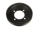 2006 Chrysler Sebring Crankshaft Pulley
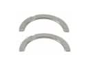 2006 Chrysler Sebring Crankshaft Thrust Washer Set
 2006 Chrysler Sebring Cylinder Head Gasket
 2006 Chrysler Sebring Dipstick
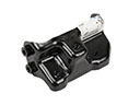 2006 Chrysler Sebring Engine Mount Bracket
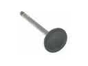 2006 Chrysler Sebring Intake Valve
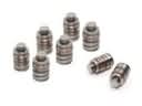 2006 Chrysler Sebring Lash Adjuster
 2006 Chrysler Sebring Oil Filler Cap
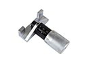 2006 Chrysler Sebring Timing Belt Tensioner
 2006 Chrysler Sebring Timing Cover Gasket