JeepParts
My Garage
My Account
Cart
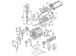
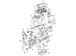
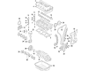
OEM 2010 Dodge Avenger Crankshaft
Crank Shaft- Select Vehicle by Model
- Select Vehicle by VIN
Select Vehicle by Model
orMake
Model
Year
Select Vehicle by VIN
For the most accurate results, select vehicle by your VIN (Vehicle Identification Number).
3 Crankshafts found

2010 Dodge Avenger Crankshaft Part Number: 4663638
$1000.64 MSRP: $1485.00You Save: $484.36 (33%)Ships in 1-2 Business DaysProduct Specifications- Other Name: Crankshft
- Item Weight: 51.50 Pounds
- Item Dimensions: 22.5 x 8.0 x 7.8 inches
- Condition: New
- Fitment Type: Direct Replacement
- SKU: 4663638
- Warranty: This genuine part is guaranteed by Mopar's factory warranty.

2010 Dodge Avenger Crankshaft Part Number: 4792692AB
Product Specifications- Other Name: Crankshft
- Replaces: 4792692AC, 4792177, 4792692AA
- Item Weight: 56.60 Pounds
- Item Dimensions: 22.3 x 8.4 x 7.7 inches
- Condition: New
- Fitment Type: Direct Replacement
- SKU: 4792692AB
- Warranty: This genuine part is guaranteed by Mopar's factory warranty.

2010 Dodge Avenger Crankshaft Part Number: 68001694AC
Product Specifications- Other Name: Crankshaft - Engine; Crankshaft Kit Engine See Note; Crankshaft Package Engine; Crankshaft Kit Engine
- Replaces: 68001694AA, 4884563AC
- Item Weight: 44.60 Pounds
- Item Dimensions: 21.9 x 8.4 x 7.8 inches
- Condition: New
- Fitment Type: Direct Replacement
- SKU: 68001694AC
- Warranty: This genuine part is guaranteed by Mopar's factory warranty.
2010 Dodge Avenger Crankshaft Parts and Q&A
- Q: What Are the Steps Involved in Installing a Crankshaft on 2010 Dodge Avenger?A: Five main bearings keep the crankshaft from moving and only the upper shells of the bearings in the crankcase have grooves and holes for carrying oil, while the lower shells are plain. Two-piece thrust bearings are used to control crankshaft end play on a specific main bearing journal. You should first use Mopar brake parts cleaner and blow out the holes in the main bearing cap bolts with compressed air. When fitting the upper bearing shells, match their lubrication groove and oil hole with the same position in the engine block, so the holes in both line up. After machine work is done on the crankshaft, it must be balanced together with the target ring. Use Mopar brake parts cleaner to wipe down the crankshaft and target ring and dry them off with compressed air. Every time you install the target ring, use fresh mounting screws and install them just snug in the #1 placing, checking that they are engaged properly before tightening all screws to 13 Nm (110 in-lbs). Put trans gel on the outside of the thrust bearings and make sure the notches are all facing the crankshaft. Install the thrust bearings in the block, always making sure that no oil gets on the part where the ladder connects to the frame. Before installing the crankshaft, dry and clean the cap bolt holes for the main bearing, oil the engine bearings and journals, then make sure the bearing surfaces are well lubricated. Lay the lower main bearings into the main bearing cap so that the bearing tabs rest correctly in their seats. Put the main bearing caps onto the engine block, checking that the threads are free of dirt and grease before putting in the main bearing cap bolts loosely. Correct alignment of the thrust bearing calls for rotating the crankshaft until number 4 piston is at TDC, moving the crankshaft to its rear limit, then to its forward limit and fixing an appropriate tool behind the rear of the cylinder block and in front of the crankshaft counterweight to lock it in place. Locate the bolt heads so you can find the accurate torque that should be used, as these vary with each different set of main bolts. To tighten the bolts according to their type, first use 15 Nm (11 ft. lbs.), then 27 Nm (20 ft. lbs.) and rotate another 45° or go from 15 Nm (11 ft. lbs.), to 45 Nm (33 ft. lbs.) and rotate again by 45°. After getting rid of the wedge tool, check the turning torque which has to remain under 5.6 Nm and examine crankshaft end play. Were not to reuse bolt: Connecting rod bearings and caps can be inserted and they should be tightened to 20 Nm + 90° (15 ft. lbs.) + 90°. Attach the ladder frame assembly, balance shaft module, crankshaft position sensor and cylinder head in its original place. Now place the front crankshaft sprocket, timing chain, timing chain front cover and oil pan onto the block. Fit the rear crankshaft seal, along with the front seal, plus the mount support bracket and vibration damper for the engine. Place the water pump pulley, remove the engine from the stand and hook the chain to the engine lift. Mount the crankshaft rear oil seal and the drive plate/flex plate with new screws and tighten them to 95 Nm (70 ft. lbs.) Attach the transaxle to the engine and tighten the bellhousing bolts to 101 Nm (75 ft. lbs.), before mounting the engine assembly. After that, place a new oil filter, pour in the oil, add coolant, start the engine, check for drips and put on the cover.
Related 2010 Dodge Avenger Parts
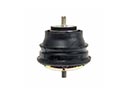 2010 Dodge Avenger Engine Mount
 2010 Dodge Avenger Timing Belt
 2010 Dodge Avenger Cam Gear
 2010 Dodge Avenger Cylinder Head
 2010 Dodge Avenger Dipstick Tube
 2010 Dodge Avenger Oil Filler Cap
 2010 Dodge Avenger Oil Pump
 2010 Dodge Avenger Piston Ring Set
 2010 Dodge Avenger Timing Belt Tensioner
 2010 Dodge Avenger Timing Cover Gasket
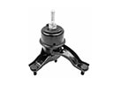 2010 Dodge Avenger Transmission Mount
 2010 Dodge Avenger Valve Stem Seal