JeepParts
My Garage
My Account
Cart
OEM Chrysler Concorde Axle Shaft
Car Axle Shaft- Select Vehicle by Model
- Select Vehicle by VIN
Select Vehicle by Model
orMake
Model
Year
Select Vehicle by VIN
For the most accurate results, select vehicle by your VIN (Vehicle Identification Number).
7 Axle Shafts found

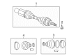
Chrysler Concorde Axle Assembly, Front Driver Side Part Number: 4882517
$125.95 MSRP: $578.00You Save: $452.05 (79%)Ships in 1-2 Business Days
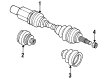
Chrysler Concorde Axle Assembly, Front Part Number: 4798098

Chrysler Concorde Axle Shafts Part Number: 4798096
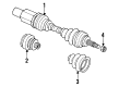
Chrysler Concorde Axle Assembly Part Number: R2073759AC
Chrysler Concorde Axle Assembly Part Number: R2073769AC
Chrysler Concorde Axle Assembly Part Number: 4798777
Chrysler Concorde Axle Shaft
Choose OEM Axle Shaft that meet Chrysler factory standards. Chrysler designs and tests every component for precision and durability. Each Axle Shaft follows strict manufacturing steps to lock in quality and fit. If your Chrysler Concorde matters to you, OEM parts make the smart choice. You'll get the exact look, feel, and performance you expect. Shop genuine Concorde parts at the highly competitive prices online. Enjoy a manufacturer's warranty, a hassle-free return policy, and rapid delivery. No more guesswork with off brands. Get genuine parts with exact fit and true factory performance. Shop with confidence today at JeepPartsDeal.com.
Axle Shaft is a very important part with exceptional reputation for quality and durability it is primarily responsible for transmission of power from the differential to the drive wheels. This design allows the wheels to turn in different direction, improve the grip when cornering hence advantageous for Chrysler Concorde that has independent suspension. The Axle Shaft is designed with long lasting steel material to generate our vehicle's stability and alignment for enduring use. It also comes in handy with Chrysler Concorde LX, LXi, and Limited trims to show that it is an essential car part that is needed to keep the vehicle running smoothly at all times. Thus, the splined ends of the axle shaft enhance easy coupling to the differential and wheel hub for efficient transfer of torque. Routine maintenance of Axle Shaft is necessary, because damaged elements could cause noise, vibrations, and failure, reducing performance and safety. Firstly, the Axle Shaft crosses the normal automobile systems due to enhanced construction and designing leading to enhanced safety of the vehicle. Being one of the critical components that contribute to the improvement of the overall driving experience, Axle Shaft remains as a representative of Chrysler Concorde cars' quality and innovativeness, which makes it one of the most crucial parts of the car model.
Chrysler Concorde Axle Shaft Parts and Q&A
- Q: How to Remove and Install an Axle Shaft on Chrysler Concorde?A:Raise the vehicle first using jackstands or a frame contact type hoist and only after that remove the front wheel and tire assembly. Fitz the front caliper unit to release it from the front Steering Knuckle, then remove the front braking disk from the wheel studs. After that, take out the speed sensor cable routing bracket from the strut and from the hub and bearing-to-stub axle nut. Open the inner tripod joint from the hub shaft retaining ring on the transaxle using a bar between the transaxle and the inner tripod with pressure being applied only to the joint. Turn the nuts on the strut assembly off the bolts, but do not turn the bolts inside the steering knuckle to stay safe. After removing the top of the steering knuckle, be sure that the flinger disk on the hub and bearing assembly has not been damaged. With the outer C/V joint assembly in one hand, spin the steering knuckle rearward and outward until the joint is not touches the hub and bearing assembly. Take the driveshaft inner tripod joint off the transaxle stub shaft by holding both the joint and interconnecting shaft and pulling on them together. During installation, first slip the new O-ring seal and the retaining circlip on the transaxle stub shaft. Then apply a thin line of grease to the O-ring seating area on the inner tripod joint close to the spline. Put the driveshaft in the hole of the splash shield and rock it to get the inner tripod joint spline connected to the stub shaft spline on the transaxle past the circlip. Put the tripod joint onto the stub shaft until it won't move further and the O-ring is not visible. You should not be able to slide the inner tripod peg if the retaining circlip is in place. Be careful not to harm the flinger disk when putting the outer C/V joint into the hub and bearing assembly. Secure the outer C/V joint assembly and twist the steering knuckle in order to fit the outer C/V joint. Ensure the top of the steering knuckle is inside the strut assembly, aligned and secure the strut with the bolts, but do not turn them as you tighten the nuts to 210 Nm (155 ft. lbs). Replace the old retaining nut at the hub and bearing assembly with a new one and tighten it loosely now. Attach the routing bracket to the front strut assembly and firmly tighten the screw provided with the bracket. Bind the braking disk onto the hub and bearing assembly, then place the front Brake Caliper over the brake disk, line it with the guides on the steering knuckle and clamp it by tightening the bolts by 22 Nm (192 inch lbs.). Production assembly personnel assemble the wheel and tire to the vehicle and then screw in the wheel mounting stud nuts in a proper sequence to half specification. Afterwards, repeat the sequence to reach the full 135 Nm (100 ft. lbs.) torque specified. Let the vehicle sit on the ground securely, press the vehicle's brakes and tighten the newly added stub shaft to hub and bearing assembly retaining nut to 142 Nm (105 ft. lbs.).
- Q: How to Service an Axle Shaft on Chrysler Concorde?A:First, lift the car off the ground using jackstands or a frame contact type hoist, then remove the front wheel and tire. Remove the front assembly from the front Steering Knuckle and pull the front disk straight off the wheel mounting studs. After that, remove the speed sensor cable bracket from the strut assembly and pull the hub and bearing off the surface where it is fastened to the stub axle retaining nut. Secure Puller, Special Tool 6790, on the hub and bearing assembly by using whell lug nuts. Screw on a needle lug nut to cover the threads on the wheel stud before prying around the outside edge of the hub with a flat blade tool. Insert a pry bar between the transaxle case and the inner tripod joint to take the inner tripod joint away from the stub shaft retaining snap ring. Untwist the attachment bolts holding the strut assembly to the steering knuckle and pull out the top of the steering knuckle. Grab the outer C/V joint assembly and swing the steering knuckle in a circle until the end of the outer C/V joint clears the hub and bearing assembly. Take the tripod joint off the transaxle stub shaft without using force on the connecting shaft to prevent separating the spider from the tripod housing. First, fit a new O-ring seal and the circlip around the stub shaft. Then, add a thin line of grease to the spline on the inner tripod joint, making sure it's even and where the O-ring sits. Place the driveshaft through where the splash shield has a hole, fit the inner tripod joint end onto the stub shaft at the transaxle, then use movement from side to side to slide past the circlip. Put the tripod joint onto the stub shaft until it doesn't move, so the O-ring remains hidden. Check the circlip's lock by pulling the inner tripod joint; if tight, the joint will not move. After fixing the C/V joint to the hub and bearing, position the top section of the steering knuckle right over the mounting holes on the strut assembly. Screw the steering knuckle attaching bolts into the strut, tightening the nuts to 169 Nm (125 ft. lbs.), while avoiding twisting the bolts in the steering knuckle. Place a new retaining nut on the hub and bearing assembly connected to the stub shaft. Tighten the nut for now, without using torque. Attach the speed sensor cable bracket back in place and put the braking disk onto both the hub and the bearing assembly. Place the Brake Caliper in front of the braking disk, connecting the caliper with the fork's mounting holes as you tighten the caliper to steering knuckle bolts using 19 Nm (168 inch lbs.). Next, fit the wheel and tire assembly, tightening each wheel mounting stud nut as described in the right sequence to a torque of 129 Nm (95 ft. lbs.). Then, lower the car, apply the brakes to hold it in place and tighten the new stub shaft to hub and bearing assembly retaining nut fully to 150 Nm (105 ft. lbs.), taking care not to over-torque.

Related Chrysler Concorde Parts
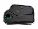 Chrysler Concorde Automatic Transmission Filter
 Chrysler Concorde Automatic Transmission Shift Levers
 Chrysler Concorde Automatic Transmission Shifter
 Chrysler Concorde CV Boot
 Chrysler Concorde Shift Cable
 Chrysler Concorde Transmission Assembly
 Chrysler Concorde Transmission Pan
Browse Chrysler Concorde Axle Shaft by Years
2004
2003
2002
2001
2000
1999
1998
1997
1996
1995
1994
1993