JeepParts
My Garage
My Account
Cart
OEM Chrysler Sebring Wheel Hub
Wheel Axle Hub- Select Vehicle by Model
- Select Vehicle by VIN
Select Vehicle by Model
orMake
Model
Year
Select Vehicle by VIN
For the most accurate results, select vehicle by your VIN (Vehicle Identification Number).
10 Wheel Hubs found


Chrysler Sebring Hub Assembly, Front Part Number: 5154211AA
$217.43 MSRP: $325.00You Save: $107.57 (34%)Ships in 1-2 Business Days


Chrysler Sebring Hub & Bearing, Front Part Number: 4578144AB
$248.54 MSRP: $318.00You Save: $69.46 (22%)Ships in 1-2 Business Days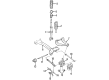
Chrysler Sebring Hub & Bearing Part Number: 4616263AA
$19.82 MSRP: $114.00You Save: $94.18 (83%)Ships in 1-2 Business Days
Chrysler Sebring Hub & Bearing, Rear Driver Side Part Number: 4766771AD
$75.99 MSRP: $337.00You Save: $261.01 (78%)Ships in 1-2 Business DaysChrysler Sebring Hub & Bearing, Rear Part Number: 4616477AB
$41.96 MSRP: $80.75You Save: $38.79 (49%)Ships in 1-2 Business Days
Chrysler Sebring Hub & Bearing, Rear Part Number: 5003550AB
$135.42 MSRP: $219.00You Save: $83.58 (39%)Ships in 1-2 Business Days
Chrysler Sebring Hub & Bearing, Rear Part Number: 4766719AC
$205.16 MSRP: $307.00You Save: $101.84 (34%)
Chrysler Sebring Hub & Bearing, Front Part Number: MR334386
$149.65 MSRP: $212.00You Save: $62.35 (30%)Ships in 1-2 Business DaysChrysler Sebring Hub Assembly Part Number: MR103654
$17.78 MSRP: $22.54You Save: $4.76 (22%)Ships in 1-2 Business Days
Chrysler Sebring Hub Assembly, Rear Part Number: MB892408
Chrysler Sebring Wheel Hub
Choose OEM Wheel Hub that meet Chrysler factory standards. Chrysler designs and tests every component for precision and durability. Each Wheel Hub follows strict manufacturing steps to lock in quality and fit. If your Chrysler Sebring matters to you, OEM parts make the smart choice. You'll get the exact look, feel, and performance you expect. Shop genuine Sebring parts at the highly competitive prices online. Enjoy a manufacturer's warranty, a hassle-free return policy, and rapid delivery. No more guesswork with off brands. Get genuine parts with exact fit and true factory performance. Shop with confidence today at JeepPartsDeal.com.
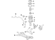
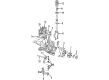
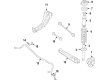
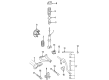
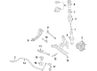
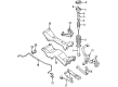
Chrysler Sebring Wheel Hub pieces spring a very important part when it comes to attaching the wheels to the vehicle and providing secure control over the direction of the car. It accommodates items like bearings and brakes hence providing easy rotation of the wheels. Even the Chrysler Sebring Wheel Hub may have different bolt patterns and different width of axle extension, therefore proper choice of replacement has to be made to fit in perfectly. The Wheel Hub that is to be installed in a Chrysler Sebring should not be general but of certain specifications that meets the car's needs, for this reason, general Wheel Hubs will not be satisfactory. The cost may be different depending on the year, model, and type of parts used but there are quality replacements sold with OE-grade at reasonable prices. These are important considerations of the Wheel Hub because the right installation ensures there are no mechanical problems that may cause havoc to the vehicle.
Chrysler Sebring Wheel Hub Parts and Q&A
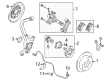
- Q: How to Service and Repair a Front Wheel Hub and Bearing on Chrysler Sebring?A:Before starting the service or repair on the front hub and bearing, lift the car, remove the wheel and tire assembly and ensure the hub nut is tightly secured so wheel bearing damage is prevented. First, tighten the hub nut when the brakes are applied; then take off the caliper, adapter, shoes and rotor from the Steering Knuckle. When the car features antilock brakes, break the bolt holding the wheel speed sensor cable routing bracket to the steering knuckle. Unfasten the nut attached to the upper ball joint stud and use Puller, Special Tool, C-3894-A to remove the upper ball joint stud from the steering knuckle, being sure not to disconnect the driveshaft inner ON joint which you must hold onto. Tip the top of the steering knuckle outward and slide the outer C/V joint out of the rear as you pull it from the hub and bearing. Next, lift the rear end of the driveshaft to protect the link from the inside. Grasp the steering knuckle and remove the three bolts fastening the hub and bearing assembly to the knuckle. Then, take the assembly out the front and tap it out if required. When installing, first wipe clean the surfaces where the bearing will be screwed on the steering knuckle, then fit the hub along with the bearing, making sure the bolt holes in each are matched. After installing the bolts, use a torque wrench to tighten them smoothly, with the reading at 110 Nm (80 ft. lbs.), to square up the bearing to the knuckle face. Insert the driveshaft C/V outsider into the driven front hub and bearing and afterward insert the upper ball joint stud into the knuckle, securing it with its nut, as shown in the diagram. Tighten the upper ball joint nut with a crow foot and torque wrench to reach 27 Nm (20 ft. lbs.). In case you have antilock brakes, attach the wheel speed sensor cable routing bracket to the steering knuckle and tighten the mounting bolt to 12 Nm (105 in. lbs.). Slide the brake rotor, caliper, shoes and adapter group back in place, then clean the outer C/V joint stub axle threads of all debris. Insert the hub nut onto the C/V joint stub axle threads and, after the vehicle brakes are applied, tighten the hub nut to 203 Nm (150 ft. lbs.). Fit the wheel and tire assembly firmly and gradually work the wheel mounting nuts in a crisscross pattern until the torque reaches 135 Nm (100 ft. lbs.). Once it is lowered, correct the front toe to the set specification.
- Q: How to Maintain and Fix a Wheel Hub on Chrysler Sebring?A:Before servicing the wheel hub, unscrew the drive shaft nut and remove the caliper, always securing its assembly with wire so it won't fall. For surgery on the upper arm, attach the tool's cord to something steady nearby and unscrew the nut, but leave it in the same spot. As you pull out the front hub assembly, ensure you use the proper tools, loosen the drive shaft bolts and lead the knuckle outward so it doesn't touch the front hub mounting bolts and ruin your ball joint or rotor. When installing, make sure the drive shaft washer is in place and use the right tool to secure the drive shaft nut, first being sure no weight is on the wheel bearings. Should the alignment of the cotter pin holes be off, tighten the nut up to 255 Nm (188 ft. lbs.) and put in the cotter pin, bending it firmly in the first two holes that do fit. To inspect the hub, mount the tool and secure it to the hub with a torque of 196 - 256 Nm (145 - 188 ft-lbs.), then test the rotation of the hub assembly to find its starting torque; it should not go over 1.0 Nm (9 inch-lbs.) and shouldn't be rough. In addition, check the front hub end play after tightening and switch out the entire front hub assembly if the play is greater than the tolerance of 0.05 mm (0.002 inch).


Related Chrysler Sebring Parts
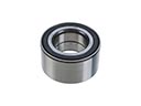 Chrysler Sebring Wheel Bearing
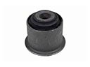 Chrysler Sebring Axle Pivot Bushing
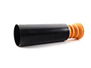 Chrysler Sebring Bump Stop
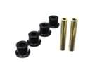 Chrysler Sebring Crossmember Bushing
 Chrysler Sebring Lateral Link
 Chrysler Sebring Lug Nuts
 Chrysler Sebring Shock Absorber
 Chrysler Sebring Steering Knuckle
 Chrysler Sebring Strut Mounts
 Chrysler Sebring Sway Bar Link Bushing
 Chrysler Sebring Sway Bars
 Chrysler Sebring Trailing Arm Bushing