JeepParts
My Garage
My Account
Cart
OEM Chrysler Sebring Steering Knuckle
Front Steering Knuckle- Select Vehicle by Model
- Select Vehicle by VIN
Select Vehicle by Model
orMake
Model
Year
Select Vehicle by VIN
For the most accurate results, select vehicle by your VIN (Vehicle Identification Number).
18 Steering Knuckles found


Chrysler Sebring Strut Mounting Fork, Front Driver Side Part Number: 4656235
$126.38 MSRP: $160.22You Save: $33.84 (22%)Ships in 1-2 Business Days

Chrysler Sebring Knuckle, Front Driver Side Part Number: MR369821
$208.22 MSRP: $239.00You Save: $30.78 (13%)Ships in 1-2 Business Days

Chrysler Sebring Knuckle, Front Driver Side Part Number: 4782903AB
$594.38Ships in 1-2 Business Days
Chrysler Sebring Knuckle, Front Passenger Side Part Number: 4766038AD
$97.82 MSRP: $187.00You Save: $89.18 (48%)Ships in 1-2 Business Days
Chrysler Sebring Knuckle, Front Passenger Side Part Number: 5085886AF
$412.10 MSRP: $556.00You Save: $143.90 (26%)Ships in 1-2 Business DaysChrysler Sebring Knuckle, Front Driver Side Part Number: 5085887AF
$424.55 MSRP: $573.00You Save: $148.45 (26%)Ships in 1-2 Business Days
Chrysler Sebring Knuckle, Rear Part Number: MR333869
$51.19 MSRP: $64.90You Save: $13.71 (22%)Ships in 1-2 Business DaysChrysler Sebring Knuckle Part Number: 4695982
$364.58 MSRP: $462.18You Save: $97.60 (22%)Ships in 1-2 Business DaysChrysler Sebring Knuckle, Rear Part Number: MR333865
Chrysler Sebring Knuckle, Rear Part Number: MR333870
Chrysler Sebring Knuckle Part Number: MR333866
Chrysler Sebring Knuckle, Front Passenger Side Part Number: MR369822
Chrysler Sebring Knuckle, Front Driver Side Part Number: 4766037AD

Chrysler Sebring Knuckle, Rear Passenger Side Part Number: 4764586AB
Chrysler Sebring Knuckle, Front Part Number: MR223628
Chrysler Sebring Knuckle, Rear Driver Side Part Number: 4764587AB
Chrysler Sebring Knuckle, Front Part Number: MR223629
Chrysler Sebring Knuckle, Front Passenger Side Part Number: 4782902AB
Chrysler Sebring Steering Knuckle
Choose OEM Steering Knuckle that meet Chrysler factory standards. Chrysler designs and tests every component for precision and durability. Each Steering Knuckle follows strict manufacturing steps to lock in quality and fit. If your Chrysler Sebring matters to you, OEM parts make the smart choice. You'll get the exact look, feel, and performance you expect. Shop genuine Sebring parts at the highly competitive prices online. Enjoy a manufacturer's warranty, a hassle-free return policy, and rapid delivery. No more guesswork with off brands. Get genuine parts with exact fit and true factory performance. Shop with confidence today at JeepPartsDeal.com.
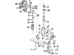
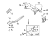
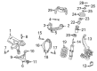
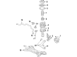
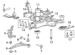
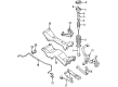
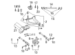
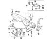
Chrysler Sebring vehicles are composed of a part known as the Steering Knuckle which transmits the suspension and steering system to the front wheels. It has provision for control arm, tie rod end and spindle or hub which allow to move vertically in relation to the road surface and to move horizontally during the process of steering. Chrysler Sebring Steering Knuckles have undergone different changes with the changes being done mainly based on the difference in the type of drive train, front-wheel drive, all-wheel drive and the rear-wheel drive. Depending on the type of the car, the drive axle is through the Steering Knuckle and in case if the car is rear-wheel drive, it may contain an integral spindle. These design variations affect the manner in which the wheel assembly is configured and its functioning with the rest of the suspension system. In general, the Steering Knuckle supports steady running of wheels and provides a correct behavior of vehicles, and its construction is appropriate for the drive type of Chrysler Sebring cars.
Chrysler Sebring Steering Knuckle Parts and Q&A
- Q: How to Service and Repair the Steering Knuckle on Chrysler Sebring?A:The first step in servicing or repairing the spindle is to raise and support the vehicle. After that, unscrew the wheel mounting nuts and lift out both the tire and the wheel. Undo the bolt that helps route the brake tube and is fitted to the brake knuckle. Working on a rear disc brake, unscrew the assembly bolts from the caliper adapter to the brake support plate, pop off the disc Brake Caliper and adapter as a unit, hang it up with a wire or bungee cord out of the way and be cautious not to overstretch the brake hose. First, remove the brake rotor or Brake Drum and afterwards the hub and bearing. After that, take the blower and release the three bolts that hold the knuckle to the trailing link. After that, get rid of the three sets of bolts: one holding the toe link to the knuckle, one connecting the lower Control Arm and one connecting the upper control arm. When these steps are done, the knuckle can be pulled out.
- Q: How is the Steering Knuckle Installed on the Front on Chrysler Sebring?A:If necessary, put the hub and bearing (1) inside the front steering knuckle first. Screw the hub and bearing (1) onto the knuckle (3) with four bolts (2), tightening them to 82 Nm (60 ft. lbs.). Should you decide to attach the shield, put it on the knuckle and tighten the three screws (2) to 10 Nm (89 in. lbs.). Slide the bearings and hub onto the splines of one half shaft outer C/V joint and then lower the ball joint stud into the mounting hole in the Control Arm. For each ball joint stud nut (4), screw in a NEW joint nut and tighten it to 95 Nm (70 ft. lbs.). The strut clevis bolts (5) have serrations, so do not turn them during installation; instead, tighten the nuts with the bolts stationary. Fix the lower end of the strut assembly onto the knuckle and install the two bolts from below. Put on the trip nuts (2) and join them to the bolts (5) by tightening until you reach 140 Nm (103 ft. lbs.). Insert the tie rod's outer tie rod (6) ball stud into the knuckle (2) arm, then screw the nut (4) onto the stud as much as you can by hand. Hold onto the stud with a wrench and tighten the nut to 85 Nm (63 ft. lbs.). Insert the wheel speed sensor head into the knuckle, add the socket screw and secure all using 12 Nm (106 in. lbs. of tightening). After that, install the brake rotor, disc Brake Caliper and adapter. Make sure the outer half shaft C/V joint is clean, then set the hub nut (1) in the end of the shaft (2) and tighten it just enough for now. As the helper keeps the hub from rotating, tighten the hub nut (3) to 132 Nm (97 ft. lbs.). Attach the wheel and tire assembly (1) by screwing on the wheel nuts to 135 Nm (100 ft. lbs.). When the job is done, set the tires using any necessary adjustments to the wheel alignment.


Related Chrysler Sebring Parts
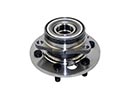 Chrysler Sebring Wheel Hub
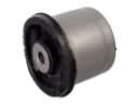 Chrysler Sebring Axle Beam Mount
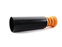 Chrysler Sebring Bump Stop
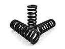 Chrysler Sebring Coil Springs
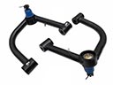 Chrysler Sebring Control Arm
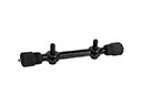 Chrysler Sebring Control Arm Shaft Kit
 Chrysler Sebring Shock Absorber
 Chrysler Sebring Shock and Strut Boot
 Chrysler Sebring Strut Bearing
 Chrysler Sebring Sway Bar Link
 Chrysler Sebring Sway Bars
 Chrysler Sebring Trailing Arm