JeepParts
My Garage
My Account
Cart
OEM 2001 Dodge Dakota Glove Box
Glove Box Compartment- Select Vehicle by Model
- Select Vehicle by VIN
Select Vehicle by Model
orMake
Model
Year
Select Vehicle by VIN
For the most accurate results, select vehicle by your VIN (Vehicle Identification Number).
2 Glove Boxes found

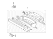 Product Specifications
- Other Name: Glove Box - Instrument Panel; Glove Box, Front
- Position: Front
- Replaces: 5GM731L8AC, 5GM731L8AE, 5GM731L8AD
- Item Weight: 5.50 Pounds
- Condition: New
- Fitment Type: Direct Replacement
- SKU: 5GM73WL8AE
- Warranty: This genuine part is guaranteed by Mopar's factory warranty.
- Product Specifications
- Other Name: Glove Box - Instrument Panel; Glove Box, Front
- Position: Front
- Replaces: 5GM731DVAD, 5GM731DVAE, 5GM731DVAC
- Item Weight: 4.30 Pounds
- Item Dimensions: 20.2 x 10.2 x 10.6 inches
- Condition: New
- Fitment Type: Direct Replacement
- SKU: 5GM73XDVAE
- Warranty: This genuine part is guaranteed by Mopar's factory warranty.
2001 Dodge Dakota Glove Box Parts and Q&A
- Q: How to Remove and Reinstall a Glove Box Module on 2001 Dodge Dakota?A: First, captors disconnect the negative battery cable to deactivate the air bag. This takes two minutes to allow the capsules to completely finish discharging. First, get rid of the cluster bezel and then remove the lower bezel. After that, unbolt the screw holding the inboard glove box module to the instrument panel inside the lower bezel and remove the end cap from the passenger side. Take away the single screw on the right next to the passenger side end cap and loosen the four screws under the glove box frame. Release the latch and open the glove box and then remove the latch striker from the upper part of the box opening. Later, remove the two screws that are still holding the glove box module in place at the top of the upper glove box opening reinforcement. If your vehicle comes with a glove box lamp, pull the glove box module out of the instrument panel and disconnect the wire harness connector for the glove box lamp and switch from the receptacle inside the glove box. When setting up, place the glove box module on the instrument panel and link the wire harness connector from the instrument panel to the connector for the glove box lamp and switch in the same location if there is one. Place the top of the glove box module against the upper reinforcement for the opening and then install and tighten the two outside screws to 2 N.m (20 in. lbs.). Place the latch striker into the glove box, securely close the glove box and make sure the four captive screws holding the bottom of the module to the instrument panel are tightened to 2 N.m (20 in. lbs.). Hook the lower brace onto the glove box module at the outboard end, tighten the screw as far as it can go to 2 N.m (20 in. lbs.) and reattach the passenger side end cap after that. After that, mount the screw on the inner side of the glove box module to the instrument panel behind the lower bezel to a tightness of 2 N.m (20 in. lbs.), check the glove box hinges are working and that everything is aligned, place the lower bezel and cluster bezel back onto the instrument panel and reattach the battery's negative cable.
Related 2001 Dodge Dakota Parts
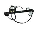 2001 Dodge Dakota Window Regulator
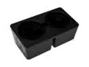 2001 Dodge Dakota Cup Holder
 2001 Dodge Dakota Door Latch Assembly
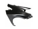 2001 Dodge Dakota Fender
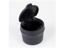 2001 Dodge Dakota Ashtray
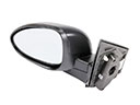 2001 Dodge Dakota Car Mirror
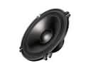 2001 Dodge Dakota Car Speakers
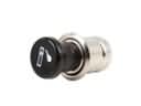 2001 Dodge Dakota Cigarette Lighter
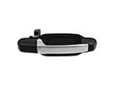 2001 Dodge Dakota Door Handle
 2001 Dodge Dakota Door Lock
 2001 Dodge Dakota Trunk Lid Latch
 2001 Dodge Dakota Window Run