JeepParts
My Garage
My Account
Cart
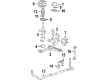
OEM 2004 Chrysler Pacifica Steering Knuckle
Front Steering Knuckle- Select Vehicle by Model
- Select Vehicle by VIN
Select Vehicle by Model
orMake
Model
Year
Select Vehicle by VIN
For the most accurate results, select vehicle by your VIN (Vehicle Identification Number).
2 Steering Knuckles found

2004 Chrysler Pacifica Knuckle, Front Passenger Side Part Number: 4743144AB
$334.34 MSRP: $414.00You Save: $79.66 (20%)Ships in 1-2 Business DaysProduct Specifications- Other Name: Knuckle - Front; Steering Knuckle, Front Right; Knuckle Front
- Position: Front Passenger Side
- Item Weight: 7.00 Pounds
- Item Dimensions: 13.4 x 10.2 x 4.3 inches
- Condition: New
- Fitment Type: Direct Replacement
- SKU: 4743144AB
- Warranty: This genuine part is guaranteed by Mopar's factory warranty.
- Product Specifications
- Other Name: Knuckle - Front; Steering Knuckle, Front Left; Knuckle Front
- Position: Front Driver Side
- Item Weight: 7.10 Pounds
- Item Dimensions: 13.4 x 10.4 x 4.3 inches
- Condition: New
- Fitment Type: Direct Replacement
- SKU: 4743145AB
- Warranty: This genuine part is guaranteed by Mopar's factory warranty.
2004 Chrysler Pacifica Steering Knuckle Parts and Q&A
- Q: How to Remove and Install a Steering Knuckle on 2004 Chrysler Pacifica?A: Raise and support the vehicle first, then remove the wheel and tire before getting rid of the front steering knuckle. After that, remove the cotter pin, nut lock and spring washer from the end of the halfshaft stub shaft and the hub nut. With one person braking the hub assembly, remove the hub nut. Get past the front brake rotor and after that, unclip the wheel speed sensor's wire from the connector and pull it free from the outer frame rail reinforcement. Disconnect the screw fixing the wheel speed sensor routing bracket to the strut, open the clip on the knuckle and the sensor will be free to remove. Press the end of the halfshaft stub shaft to pull the splines out of the hub splines. Loosen the nut joining the outer tie rod to the steering knuckle first, holding the outer tie rod stud in place and afterwards use Remover, Special Tool C-3894-A to take off the tie rod from the steering knuckle. Take out the bolts that hold the strut clevis to the steering knuckle, move the knuckle outward to free the halfshaft stub shaft from the hub and bearing and hang the driveshaft straight outward. Remove the ball joint nut with a power impact wrench and then put the nut back so it sits even with the stud on the ball joint. Push Place Remover, Special Tool C-4150A onto the ball joint stud and nut, tighten the tool screw-drive to remove the stud from the steering knuckle and let the tool fall. Pull the tools as well as the nut out and release the steering knuckle from the underside of the car. Any time the hub and bearing are changed, first remove the bolts that attach them to the knuckle. Look over the knuckle for any cracks, dents or signs of stress; if they exist, the knuckle needs replacing. If installing the hub and bearing in the knuckle, put them in the central hole with the wheel speed sensor toward the rear, align the threaded holes on all sides and use a crisscross pattern to tighten the bolts to 65 Nm (45 ft. lbs.). You should wipe down the ball joint stud's contact area to prevent possible damage when installing the knuckle. Fit the knuckle to the ball joint stud, attach a new nut, tighten with a crowfoot wrench to 81 Nm (60 ft. lbs) and then turn the nut 1/4 more. Firmly join the halfshaft stub shaft to the hub and bearing assembly, but hold off on turning the attaching bolts for the steering knuckle to strut assembly. Put in the attaching bolts for the strut clevis to the steering knuckle, tightening them to 81 Nm (60 ft. lbs.) and turning them an additional one-quarter turn. Before inserting the outer tie rod stud into the knuckle arm, wipe clean the tie rod stud stud and arm contact point. Then, put the nut on the stud and tighten it to 47 Nm (35 ft. lbs.) with an extra 1/2 turn. After placing the wheel speed sensor cable grommet in the clip at the knuckle and clamping it down, next attach the routing bracket for the wheel speed sensor to the strut and tighten the screw so that the torque value ranges from 13 Nm to 115 inch lbs. Connect the wire clip and the sensor connector to the reinforcement, fit the vehicle wiring to the sensor and attach the brake rotor before putting on the disc brake caliper and adapter. Let the sensor cable for the wheel speed be far from any parts such as the rotor that are in motion. Attach the washer and hub nut to the halfshaft stub shaft and use a helper to tighten to 244 Nm (180 ft. lbs.) while they apply the brakes. Afterward, put in the spring washer and hub nut lock and secure it with a replacement cotter pin. After that, mount the tire and wheel, tighten the wheel mounting nuts to 135 Nm (100 ft. lbs.), lower the vehicle, cause the brakes to retract, check the brake fluid level and adjust it if required, then carry out a wheel alignment.
Related 2004 Chrysler Pacifica Parts
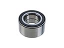 2004 Chrysler Pacifica Wheel Bearing
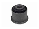 2004 Chrysler Pacifica Axle Pivot Bushing
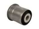 2004 Chrysler Pacifica Axle Support Bushings
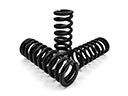 2004 Chrysler Pacifica Coil Springs
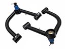 2004 Chrysler Pacifica Control Arm
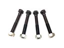 2004 Chrysler Pacifica Control Arm Bolt
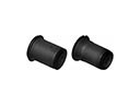 2004 Chrysler Pacifica Control Arm Bushing
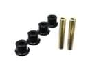 2004 Chrysler Pacifica Crossmember Bushing
 2004 Chrysler Pacifica Lateral Link
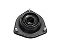 2004 Chrysler Pacifica Shock And Strut Mount
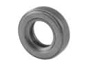 2004 Chrysler Pacifica Strut Bearing
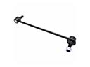 2004 Chrysler Pacifica Sway Bar Link