JeepParts
My Garage
My Account
Cart
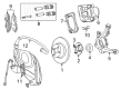
OEM 2005 Dodge Neon Steering Knuckle
Front Steering Knuckle- Select Vehicle by Model
- Select Vehicle by VIN
Select Vehicle by Model
orMake
Model
Year
Select Vehicle by VIN
For the most accurate results, select vehicle by your VIN (Vehicle Identification Number).
5 Steering Knuckles found


2005 Dodge Neon Knuckle, Front Driver Side Part Number: 5272487AC
$242.25 MSRP: $318.00You Save: $75.75 (24%)Ships in 1-2 Business DaysProduct Specifications- Other Name: Knuckle - Front; Steering Knuckle, Front Left
- Position: Front Driver Side
- Replaces: 5272487AB
- Item Weight: 12.00 Pounds
- Item Dimensions: 10.3 x 10.5 x 5.9 inches
- Condition: New
- Fitment Type: Direct Replacement
- SKU: 5272487AC
- Warranty: This genuine part is guaranteed by Mopar's factory warranty.


2005 Dodge Neon Knuckle, Front Passenger Side Part Number: 5272486AC
$213.00 MSRP: $316.00You Save: $103.00 (33%)Ships in 1-3 Business DaysProduct Specifications- Other Name: Knuckle - Front; Steering Knuckle, Front Right
- Position: Front Passenger Side
- Replaces: 5272486AB
- Item Weight: 10.90 Pounds
- Item Dimensions: 10.5 x 10.4 x 6.0 inches
- Condition: New
- Fitment Type: Direct Replacement
- SKU: 5272486AC
- Warranty: This genuine part is guaranteed by Mopar's factory warranty.


2005 Dodge Neon Knuckle, Front Part Number: 4656090AF
Product Specifications- Other Name: Knuckle - Front; Knuckle Front
- Position: Front
- Condition: New
- Fitment Type: Direct Replacement
- SKU: 4656090AF
- Warranty: This genuine part is guaranteed by Mopar's factory warranty.
2005 Dodge Neon Knuckle, Front Driver Side Part Number: 4656939AC
Product Specifications- Other Name: Knuckle - Front; Steering Knuckle, Front Left
- Position: Front Driver Side
- Replaces: 4656939AB
- Item Weight: 10.10 Pounds
- Condition: New
- Fitment Type: Direct Replacement
- SKU: 4656939AC
- Warranty: This genuine part is guaranteed by Mopar's factory warranty.
2005 Dodge Neon Knuckle, Front Part Number: 4656938AC
Product Specifications- Other Name: Knuckle - Front
- Position: Front
- Replaces: 4656938AB
- Item Weight: 11.00 Pounds
- Condition: New
- Fitment Type: Direct Replacement
- SKU: 4656938AC
- Warranty: This genuine part is guaranteed by Mopar's factory warranty.
2005 Dodge Neon Steering Knuckle Parts and Q&A
- Q: How to Remove and Replace a Steering Knuckle on 2005 Dodge Neon?A: Begin by pressing the brakes and holding them in position, raise the car and after that, the front tire and wheel assembly should be removed. After that, take off the cotter pin, lock nut and spring washer from the hub nut and with the brakes on, turn the hub nut slightly to loosen it. Let go of the brakes and release the two bolts that tie the front disc caliper to the steering knuckle. Move the caliper at an angle toward the rotor and remove it from its slide. Remove the caliper from its normal spot so it doesn't dangle by the hose, then remove the retaining clips and pull the rotor off its hub. Hold the tie rod end stud with a wrench and loosen and remove the nut that connects the outer tie rod to the steering knuckle. With Remover, Special Tool MB991113, loosen the tie rod end from the steering knuckle and take out the tie rod heat shield. Following this, remove the nut and clamp bolt that keeps the ball joint stud attached to the steering knuckle, as you don't want to move the bolts holding the strut assembly and steering knuckle together. Draw each steering knuckle bolt out with a pin punch and screwdriver, so you do not damage the ball joint seal. To remove the ball joint stud, press down on the lower control arm and upward against the boss of the steering knuckle. With the driveshaft supported, remove tension from the inner C/V joint so it won't come apart and then pull the steering knuckle away from the outer C/V joint splines on the driveshaft. Whenever replacing the steering knuckle, remove the hub and wheel bearing and discard the wheel bearing, not using it again. For disassembly, take out the steering knuckle, hub and wheel bearing together and then use Remover, Special Tool 4150A, to force one wheel mounting stud out through the hub flange. Adjust the hub so that the stud lines up with the notch in the bearing retainer plate and take off that stud. Fit half of Bearing Splitter, Special Tool 1130, between the hub and the retainer plate, so it is aligned with the caliper rail on the steering knuckle. Put the remaining elements of Bearing Splitter onto the steering knuckle and tighten the nuts with your hands. Once the three bolts on the bearing retainer plate are pressing on the bearing splitter, support the steering knuckle in an arbor press by means of the bearing splitter. Set Driver, Special Tool 6644-2, onto the small end of the hub, then use the arbor press to get the hub out of the bearing. Take out the bearing splitter and the three bolts that hold the bearing retainer plate. Once that's done, use Bearing Driver, Special Tool MB-990799 to press the wheel bearing out of the steering knuckle. Put the steering knuckle on its side, clean the open bore, place the bearing into the bore and press it into place using Driver, Special Tool 5052. Insert the bearing retainer plate and then tighten the mounting bolts with a torque of 28 Nm (250 inch lbs.). After removing the wheel mounting stud from the bearing, put it back into the hub flange and press until fully seated. Remove the wheel bearing from the steering knuckle, position the knuckle back in the arbor press and press the hub into the bearing until the hub is fully in. Put together the steering knuckle assembly in the vehicle by mounting the hub on the C/V joint splines on the driveshaft and lining the ball joint stud with the knuckle boss. Replace the ball joint stud with a new pinch bolt and nut and tighten them to 95 Nm (70 ft. lbs.). Guide the strut into place on the steering knuckle and secure it with the two bolts, making the nuts firm by spinning them 53 Nm (40 ft. lbs.) and an extra 90° turn. Install the ball stud in the steering knuckle arm by hand and then attach the heat shield on the front tie rod, tightening the nut by torque wrench up to 55 Nm (40 ft. lbs.). Fit the brake rotor to the hub, putting the disc brake caliper on next and secure both with the two guide pin bolts tightened to a torque of 22 Nm (192 inch lbs.). Clean the threads of the driveshaft outer C/V joint, put in the hub nut and tighten it to 244 Nm (180 ft. lbs.), using the brakes while tightening. Subsequently, install a spring washer, lock nut and cotter pin on the hub nut, then cross the ends of the cotter pin around the lock nut, set the tire and wheel in place, tighten the wheel mounting nuts to a torque of 135 Nm (100 ft. lbs.), lower the vehicle and check the toe measurement.
Related 2005 Dodge Neon Parts
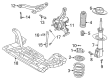
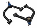 2005 Dodge Neon Control Arm
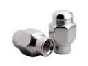 2005 Dodge Neon Lug Nuts
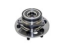 2005 Dodge Neon Wheel Hub
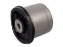 2005 Dodge Neon Axle Beam Mount
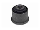 2005 Dodge Neon Axle Pivot Bushing
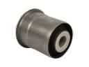 2005 Dodge Neon Axle Support Bushings
 2005 Dodge Neon Coil Spring Insulator
 2005 Dodge Neon Coil Springs
 2005 Dodge Neon Control Arm Bushing
 2005 Dodge Neon Shock And Strut Mount
 2005 Dodge Neon Sway Bar Kit
 2005 Dodge Neon Sway Bar Link