JeepParts
My Garage
My Account
Cart
OEM Dodge Neon Steering Knuckle
Front Steering Knuckle- Select Vehicle by Model
- Select Vehicle by VIN
Select Vehicle by Model
orMake
Model
Year
Select Vehicle by VIN
For the most accurate results, select vehicle by your VIN (Vehicle Identification Number).
13 Steering Knuckles found


Dodge Neon Knuckle, Front Driver Side Part Number: 4656091AE
$132.20 MSRP: $218.00You Save: $85.80 (40%)Ships in 1-2 Business Days


Dodge Neon Knuckle, Front Passenger Side Part Number: 5272486AC
$213.00 MSRP: $316.00You Save: $103.00 (33%)Ships in 1-3 Business Days


Dodge Neon Knuckle, Front Driver Side Part Number: 5272487AC
$242.25 MSRP: $318.00You Save: $75.75 (24%)Ships in 1-2 Business Days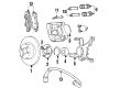
Dodge Neon Knuckle, Front Part Number: 4897928AB
$120.97 MSRP: $255.00You Save: $134.03 (53%)Ships in 1-2 Business DaysDodge Neon Knuckle, Front Passenger Side Part Number: 4656090AE
$194.86 MSRP: $320.00You Save: $125.14 (40%)Ships in 1-2 Business Days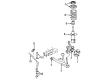
Dodge Neon Knuckle, Front Part Number: 4897928AA
$172.73 MSRP: $255.00You Save: $82.27 (33%)Ships in 1-2 Business Days
Dodge Neon Knuckle, Front Part Number: 4656090AF
Dodge Neon Knuckle, Front Part Number: 4897929AB
Dodge Neon Knuckle Part Number: 4897663AB
Dodge Neon Knuckle Part Number: 4897662AB
Dodge Neon Knuckle Part Number: 4656938AA
Dodge Neon Knuckle, Front Part Number: 4656938AC
Dodge Neon Knuckle, Front Driver Side Part Number: 4656939AC
Dodge Neon Steering Knuckle
Choose OEM Steering Knuckle that meet Dodge factory standards. Dodge designs and tests every component for precision and durability. Each Steering Knuckle follows strict manufacturing steps to lock in quality and fit. If your Dodge Neon matters to you, OEM parts make the smart choice. You'll get the exact look, feel, and performance you expect. Shop genuine Neon parts at the highly competitive prices online. Enjoy a manufacturer's warranty, a hassle-free return policy, and rapid delivery. No more guesswork with off brands. Get genuine parts with exact fit and true factory performance. Shop with confidence today at JeepPartsDeal.com.
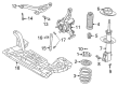
The Steering Knuckle found in Dodge Neon cars plays a very important role since it links the suspension system to the steering and front wheels. It gives axially configured locations for control arms, tie-rod ends, spindles or hubs allowing vertical motion according to road surface inputs and lateral motion during steering. The classification of Dodge Neon Steering Knuckles can be made dependent upon the drive layouts that are different from one another and principally include FWD or front-wheel drive as well as AWD or all-wheel drive. In FWD/AWD models, the drive axle goes through the Steering Knuckle that is either fastened by bolts or pressed into the hub. The design variations are aimed at making the wheel assembly rotate in a stable manner while at the same time having control and stability during its operation. Dodge Neon vehicles benefit from frequent inspections of the Steering Knuckle and associated components as do other automobile makes and models.
Dodge Neon Steering Knuckle Parts and Q&A
- Q: How to Service and Repair a Steering Knuckle on Dodge Neon?A:The steering knuckle, the hub and the Wheel Bearing should all be taken out together from the car before you continue. Push the Remover, Special Tool 4150A, on one stud, take the stud out of the hub flange and turn the hub so the removed stud fits onto the hole of the bearing retainer plate, then pull the stud out. Rotate the hub so the missing stud hole faces the opposite direction from the brake caliper lower rail on the steering knuckle, insert one half of Bearing Splitter, Special Tool 1130, between the hub and the bearing retainer plate and match the threaded hole with the rail. Afterwards, attach Special Tool 1130 to the steering knuckle and tighten the nuts by hand. The three bolts that fix the retainer plate to the steering knuckle should touch the bearing splitter, but not lift it up. Support the steering knuckle in an arbor press on the bearing splitter, add the Special Tool 6644-2 Driver to the small hub end and use the arbor press to drive out the hub and the outer bearing race from the wheel bearing. Unbolt the three mounting bolts for the bearing retainer plate and remove the splitter piece, then remove the retainer plate. After placing the steering knuckle back in the arbor press, add press blocks that do not touch the inside of the knuckle and use the Bearing Driver, Special Tool MB-990799, to remove the wheel bearing. Slide Bearing Splitter, Special Tool 1130, over the hub between the flange and the outer race and then carefully use Driver, Special Tool 6644-2 to press the hub out from the outer race. Open the steering knuckle, use a dry shop cloth to clean its bore, fit the new wheel bearing straight inside and work it into place with Receiver, Special Tool C-4698-2 and Driver, Special Tool 5052. Paper fasten the retainer plate using the original or matching replacement bolts, but fasten them no tighter than 28 Nm (250 inch lbs.). Put the wheel mounting stud into the hub flange again and push it until it sits fully inside, then set the steering knuckle bearing part back into the arbor press with Receiver and Special Tool MB-990799 supporting the inner race. Guarantee that the hub is square on the inside of the bearing and press the hub into the bearing to the bottom. After that, put the steering knuckle assembly back into position on the vehicle.
- Q: How to Remove and Install a Steering Knuckle on Dodge Neon?A:To take out the steering knuckle, apply the brakes, then raise the car and remove the whole front wheel assembly. Then, pull the small pin, lock nut and spring washer from the hub nut and while braking, unscrew and take out the hub nut before stop braking. Remove both bolts holding the front disc Brake Caliper to the steering knuckle, tip the caliper upper or lower away from the rotor by the slide and pull it off the other end of the slide and rotor. Disconnect the caliper and suspend it out of the way, making certain the hose is not holding the weight. Remove any hold-down clips from the wheels and take off the brake rotor at the front hub next. Then, hold the tie rod end stud in place with a wrench, twist off the nut using a standard or crowfoot wrench and pull the tie rod end off the steering knuckle using Remover, Special Tool MB991113. Finally, remove the heat shield from the tie rod. Grasp the pinch bolt and nut on the ball joint stud and carefully loosen them. While you are doing this, press the serrated attaching bolts between the strut and steering knuckle to keep them from turning, then tap the pinch bolts out with a pin punch. Get rid of the bolts binding the strut to the steering knuckle without cutting the ball joint seal by prying the stud up and the lower arm down toward the ball joint boss. Make sure the supports are under the driveshaft so the inner joint on the ON does not come apart and then release the steering knuckle from the splines of the driveshaft outer C/V joint. Since it's not possible to transfer the cartridge type front Wheel Bearing, make sure to remove the hub and wheel bearing before changing the steering knuckle. For taking the parts apart, first remove the steering knuckle, hub and wheel bearing as a set, then insert Remover, Special Tool 41 50A, into the outer hub flange to press out a stud that is aligned with the notch in the bearing retainer plate. Insert Special Tool 1130, half of the bearing splitter, between the hub and bearing retainer plate, so its threaded hole lines up with the caliper rail on the steering knuckle, then install and tighten the other parts of the bearing splitter by hand. Make certain the three bolts securing the bearing retainer plate to the steering knuckle touch the bearing splitter and use an arbor press to mount the steering knuckle while resting it on the bearing splitter. Place Special Tool 6644-2 on the little end of the hub and press it with the arbor press until the hub and outer race are removed from the wheel bearing. With the bearing splitter and the three bolts out, you should press the wheel bearing out of the steering knuckle with the Bearing Driver, Special Tool MB-990799. Before assembly, clear any dirt from the steering knuckle bore, insert the wheel bearing and use Driver, Special Tool 5052 to press it in all the way. Fit the bearing retainer plate and tighten the three bolts to an even torque of 28 Nm (250 inch lbs.). Patch the wheel stud back into the hub flange and push it well, then bring the steering knuckle and wheel bearing back to the arbor press and press the hub directly into the rear of the wheel bearing. Installing the steering knuckle first, slide the hub over the splines of the C/V joint, match the ball joint stud with the steering knuckle, place a pinch bolt and nut and tighten the nut to a torque of 95 Nm (70 ft. lbs.). Place the lower section of the strut assembly directly above the upper part of the steering knuckle and put the bolts through the holes, facing the front of the car as you tighten them to 53 Nm (40 ft. lbs.) more turn by hand. Set the heat shield onto the steering knuckle arm, slide the outer tie rod ball stud into place and tighten the nut using 55 Nm (40 ft. lbs.) of force. First, attach the brake rotor to the hub, then fit the disc brake caliper onto the rotor and steering knuckle, using the two guide pin bolts. Fasten the bolts to a torque of 22 Nm (192 lb. in.) Wash the driveshaft C/V joint threads and fit the hub nut on them, tightening it 244 Nm (180 ft. lbs.) with the brakes on. Finally, put the spring washer, lock nut and cotter pin on the hub nut, then wrap the cotter pin ends around the lock nut, put on the tire and wheel assembly, tighten the wheel mounting nuts to 135 Nm (100 ft. lbs.), lower the vehicle and adjust the toe of the wheel to specification.


Related Dodge Neon Parts
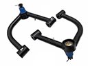 Dodge Neon Control Arm
 Dodge Neon Lug Nuts
 Dodge Neon Wheel Bearing
 Dodge Neon Axle Beam Mount
 Dodge Neon Axle Pivot Bushing
 Dodge Neon Bump Stop
 Dodge Neon Coil Spring Insulator
 Dodge Neon Coil Springs
 Dodge Neon Lateral Link
 Dodge Neon Suspension Strut Rod
 Dodge Neon Sway Bar Bushing
 Dodge Neon Sway Bar Link Bushing