JeepParts
My Garage
My Account
Cart
OEM 2006 Chrysler Town & Country Rack And Pinion
Steering Rack And Pinion- Select Vehicle by Model
- Select Vehicle by VIN
Select Vehicle by Model
orMake
Model
Year
Select Vehicle by VIN
For the most accurate results, select vehicle by your VIN (Vehicle Identification Number).
1 Rack And Pinion found


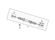
2006 Chrysler Town & Country Steering Gear Part Number: R8072216AC
$746.97 MSRP: $869.00You Save: $122.03 (15%)Product Specifications- Other Name: Gear - Rack And Pinion; Rack and Pinion Assembly; Steering Gearbox; Gear Assembly; Gear Rack And Pinion With Tie Rod Ends; Gear Rack And Pinion
- Replaces: 68072216AC, 68072216AA, 4766250AF, 4766260AK, 4766250AG, 4766250AN, 4766260AL, 4766270AC, 4766250AL, 4766260AJ, 4766250AM, 4766260AG, 4766250AK, 68072216AB, 4766260AF, 4766260AM, R0400272
- Item Weight: 19.90 Pounds
- Item Dimensions: 61.8 x 11.6 x 6.4 inches
- Condition: New
- Fitment Type: Direct Replacement
- SKU: R8072216AC
- Warranty: This genuine part is guaranteed by Mopar's factory warranty.
2006 Chrysler Town & Country Rack And Pinion Parts and Q&A
- Q: How to Service a Rack and Pinion in RHD Steering Systems on 2006 Chrysler Town & Country?A: Service the RHD rack and pinion by opening the reservoir cap and extracting most of the fluid with a siphon pump. Lock the steering column straight to prevent the rubber coupler from stretching too far when you connect or disconnect. Put the steering wheel straight in front of you and hold it with a steering wheel maintenance tool. When the vehicle is on the ground, take off the steering column coupler from the rack and pinion intermediate shaft. Depress the brake pedal with a depressor so that the pedal is locked past the first inch, stopping fluid from escaping from the master cylinder as you loosen the brake tubes. After you've raised the vehicle, take out the front wheel and tire assemblies. When your car has a power steering cooler, take off one of the hoses so that you can drain the fluid. Pull the antilock brake integrated control unit (ICU) and brake tubes out of the routing clips placed on the crossmember reinforcement. On each of the steering tie rod ends, take off the nut that joins the tie rod end to the knuckle. Hold the tie rod end stud with a socket and use a wrench to loosen the nut. You should remove both tie rod ends from the steering knuckles by using Puller, Special Tool C-3894-A. On each side, take out the lower control arm rear bushing retainer bolts and remember that the thread sizes differ on the cradle crossmember reinforcement bolts. Take off the cradle crossmember reinforcement from the front suspension cradle as well as from the vehicle's body. Take out the pressure and return hoses from the rack and pinion and unbolt the clamp holding them to the cradle crossmember. Remove the heat shield from the rack and pinion plus the bolts and nuts holding the rack and pinion to the front suspension cradle. Take the rack and pinion out enough so the intermediate shaft coupler roll pin is within reach and then use Remover/Installer, Special Tool 6831 A, to pull the roll pin easy. Remove the rack and pinion shaft from the coupler and take out the power steering rack and pinion from the car. During installation, place the rack and pinion in the front suspension cradle crossmember and reserve area for the intermediate coupler. Put the roll pin inside the intermediate shaft coupler, then drive it in with a hammer. Remove and insert the pin using Remover/Installer Special Tool 6831A. Following the sequence, install the rack and pinion on the front suspension cradle, secure it with the two M-14 size bolts and the nuts and tighten the bolts to 183 Nm (135 ft. lbs.) and 95 Nm (70 ft. lbs.), respectively. Fit the heat shield onto the rack and pinion and join both ends of the power steering hoses loosely. Routing clamp bolts should be used to secure the hoses. Strengthen each power steering fluid hose tube screw at the rack and pinion by tightening it to 31 Nm (275 in. lbs.), operating a crowfoot wrench with a torque wrench. Attach the tie rod end to the steering knuckle, tighten the holding nut with the stud still and finish with a torque of 75 Nm (55 ft. lbs.). Mount the reinforcement on the front suspension cradle crossmember, using M-14 bolts at 163 Nm (120 ft. lbs.) and M-12 bolts at 108 Nm (80 ft. lbs.). Mount the lower control arm rear bushing retainer bolts and tighten them until you reach 61 Nm (45 ft. lbs.). Attach the reinforcement and rear of the cradle crossmember to the car by driving the bolts in to 163 Nm (120 ft. lbs.) tightness. Make sure the brake tubes from and to the ICU are securely connected in the routing clips and away from anything that moves. Attach the brake tubes to the clips and assure they also go into the ICU socket. If you have a power steering cooler, replace the original hose, connect it to the cooler and attach a clamp. Attach the front tire and wheel again and tighten each lug nut to 135 Nm (100 ft. lbs.). Lower your truck so you can reach the interior, but have the wheels resting above the ground. After setting the wheels straight ahead, bring the intermediate shaft into position with the steering coupler, attach the coupler to the rack and pinion intermediate shaft and screw the pinch bolt nut to 28 Nm (250 in. lbs.). Take off the steering wheel holding tool and the brake pedal depressor. Pour in clean and fresh Mopar Brake Fluid or an alternative, into the master cylinder and bleed the brake system next. Operate the system using the pump and pressure dial, follow with a clean-up, check for any leaks and then adjust the toe angle of the front wheels.
Related 2006 Chrysler Town & Country Parts
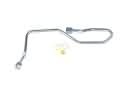 2006 Chrysler Town & Country Power Steering Hose
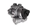 2006 Chrysler Town & Country Power Steering Pump
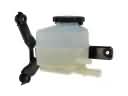 2006 Chrysler Town & Country Power Steering Reservoir
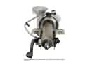 2006 Chrysler Town & Country Steering Column
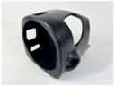 2006 Chrysler Town & Country Steering Column Cover
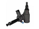 2006 Chrysler Town & Country Steering Gear Box
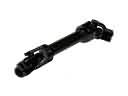 2006 Chrysler Town & Country Steering Shaft
 2006 Chrysler Town & Country Steering Wheel
 2006 Chrysler Town & Country Tie Rod End