JeepParts
My Garage
My Account
Cart
OEM 2006 Dodge Grand Caravan ABS Control Module
Anti Lock Brake Control Module- Select Vehicle by Model
- Select Vehicle by VIN
Select Vehicle by Model
orMake
Model
Year
Select Vehicle by VIN
For the most accurate results, select vehicle by your VIN (Vehicle Identification Number).
4 ABS Control Modules found


2006 Dodge Grand Caravan Modulator Valve Part Number: 5142246AA
Product Specifications- Other Name: Accumulator - Anti-Lock Brake System; ABS Hydraulic Assembly; ABS Control Module; ABS Control Unit; Hydraulic Control Unit Anti-Lock Brake System
- Item Weight: 4.50 Pounds
- Item Dimensions: 7.2 x 7.3 x 6.4 inches
- Condition: New
- Fitment Type: Direct Replacement
- SKU: 5142246AA
- Warranty: This genuine part is guaranteed by Mopar's factory warranty.


2006 Dodge Grand Caravan Control Module Part Number: 5142251AA
Product Specifications- Other Name: Control - Anti-Lock Brakes; ABS Control Module; Electronic Control; Module Anti-Lock Brakes With Mounting Screws; Module Anti-Lock Brakes
- Replaces: 5174110AA
- Item Weight: 2.20 Pounds
- Item Dimensions: 7.3 x 7.2 x 6.2 inches
- Condition: New
- Fitment Type: Direct Replacement
- SKU: 5142251AA
- Warranty: This genuine part is guaranteed by Mopar's factory warranty.


2006 Dodge Grand Caravan Control Module Part Number: 5142248AA
Product Specifications- Other Name: Control - Anti-Lock Brakes; ABS Control Module; Electronic Control; Module Anti-Lock Brakes With Mounting Screws; Module Anti-Lock Brakes
- Item Weight: 2.40 Pounds
- Item Dimensions: 7.1 x 6.8 x 6.1 inches
- Condition: New
- Fitment Type: Direct Replacement
- SKU: 5142248AA
- Warranty: This genuine part is guaranteed by Mopar's factory warranty.
2006 Dodge Grand Caravan Modulator Valve Part Number: 5142249AA
Product Specifications- Other Name: Accumulator - Anti-Lock Brake System; ABS Hydraulic Assembly; ABS Control Module; ABS Control Unit; Hydraulic Control Unit Anti-Lock Brake System
- Item Weight: 5.10 Pounds
- Item Dimensions: 7.2 x 7.0 x 6.6 inches
- Condition: New
- Fitment Type: Direct Replacement
- SKU: 5142249AA
- Warranty: This genuine part is guaranteed by Mopar's factory warranty.
2006 Dodge Grand Caravan ABS Control Module Parts and Q&A
- Q: How to Service and Repair an ABS Control Module on 2006 Dodge Grand Caravan?A: Begin by unhooking the negative cable from the battery, wrapping it in insulation and then take out the battery shield as well as the battery. Take out the bolt on the tank at the battery tray and then unwire the vacuum hose furthest from the engine to remove the battery tray. Use Mopar Brake Parts Cleaner to clean every surface and brake part inside and out to ensure dirt cannot enter the ICU. Open the antilock brake module (ABM) by pushing in the rear tabs as you pull out the lower part of the 47-way connector until it is locked. Not all vehicles have traction control, so if yours has it skip this sentence and remove five screws, otherwise remove three. Disconnect the ABM from the HCU and remove any cloth from the mating parts. If the solenoid valve stem seals or the internal pump connector O-ring are not new, swap them out and don't use any lubricant on the new seals. Place the parts together and fit the ABM onto the HCU, tightening every screw to 2 N.m (17 in. lbs.) according to if traction control is present. Once the cover is open, insert the 47-way wiring connector into the ABM and close the cover to secure it place. Reconnect the vacuum hose, shut the coolant filler neck screw securely, insert the battery to its place and set the tray and shield back in order. Last, attach the negative cable to the battery negative post, link a scan tool to start the ABM and detect any issues and test the breaks by driving the car on the road.
Related 2006 Dodge Grand Caravan Parts
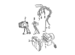
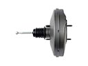 2006 Dodge Grand Caravan Brake Booster
 2006 Dodge Grand Caravan Brake Caliper
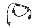 2006 Dodge Grand Caravan Speed Sensor
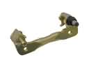 2006 Dodge Grand Caravan Brake Caliper Bracket
 2006 Dodge Grand Caravan Brake Caliper Piston
 2006 Dodge Grand Caravan Brake Disc
 2006 Dodge Grand Caravan Brake Line
 2006 Dodge Grand Caravan Brake Pad
 2006 Dodge Grand Caravan Hydraulic Hose
 2006 Dodge Grand Caravan Parking Brake Shoe
 2006 Dodge Grand Caravan Wheel Cylinder
 2006 Dodge Grand Caravan Wheel Stud