JeepParts
My Garage
My Account
Cart
OEM 2009 Dodge Charger Steering Knuckle
Front Steering Knuckle- Select Vehicle by Model
- Select Vehicle by VIN
Select Vehicle by Model
orMake
Model
Year
Select Vehicle by VIN
For the most accurate results, select vehicle by your VIN (Vehicle Identification Number).
10 Steering Knuckles found


2009 Dodge Charger Knuckle, Rear Driver Side Part Number: 4782587AF
$700.94 MSRP: $943.00You Save: $242.06 (26%)Ships in 1-2 Business DaysProduct Specifications- Other Name: Knuckle - Rear; Suspension Knuckle, Rear Left
- Position: Rear Driver Side
- Replaces: 4782587AD, 4782587AC
- Item Weight: 5.90 Pounds
- Item Dimensions: 13.4 x 9.6 x 4.3 inches
- Condition: New
- Fitment Type: Direct Replacement
- SKU: 4782587AF
- Warranty: This genuine part is guaranteed by Mopar's factory warranty.
2009 Dodge Charger Knuckle, Rear Passenger Side Part Number: 4782586AF
$609.96 MSRP: $924.00You Save: $314.04 (34%)Ships in 1-2 Business DaysProduct Specifications- Other Name: Knuckle - Rear; Suspension Knuckle, Rear Right
- Position: Rear Passenger Side
- Replaces: 4782586AD, 4782586AC
- Item Weight: 5.00 Pounds
- Item Dimensions: 13.4 x 9.8 x 4.4 inches
- Condition: New
- Fitment Type: Direct Replacement
- SKU: 4782586AF
- Warranty: This genuine part is guaranteed by Mopar's factory warranty.


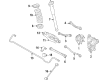
2009 Dodge Charger Knuckle, Front Driver Side Part Number: 4782741AD
Product Specifications- Other Name: Knuckle - Front; Steering Knuckle, Front Left
- Position: Front Driver Side
- Replaces: 4782741AC, 4782741AB
- Item Weight: 16.70 Pounds
- Item Dimensions: 8.0 x 9.2 x 21.9 inches
- Condition: New
- Fitment Type: Direct Replacement
- SKU: 4782741AD
- Warranty: This genuine part is guaranteed by Mopar's factory warranty.
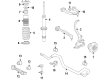
- Product Specifications
- Other Name: Knuckle - Front; Steering Knuckle, Front Right
- Position: Front Passenger Side
- Replaces: 4782740AB, 4782740AC, 4782740AA
- Item Weight: 18.10 Pounds
- Item Dimensions: 20.9 x 8.9 x 8.0 inches
- Condition: New
- Fitment Type: Direct Replacement
- SKU: 4782740AD
- Warranty: This genuine part is guaranteed by Mopar's factory warranty.
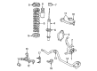
2009 Dodge Charger Knuckle, Rear Driver Side Part Number: 68248387AA
Product Specifications- Other Name: Knuckle - Rear; Suspension Knuckle, Rear Left
- Position: Rear Driver Side
- Replaces: 4854459AD, 4854459AC, 4854459AB, 4854459AA
- Item Weight: 5.60 Pounds
- Item Dimensions: 12.8 x 12.5 x 5.2 inches
- Condition: New
- Fitment Type: Direct Replacement
- SKU: 68248387AA
- Warranty: This genuine part is guaranteed by Mopar's factory warranty.
- Product Specifications
- Other Name: Knuckle - Rear; Suspension Knuckle, Rear Right
- Position: Rear Passenger Side
- Replaces: 4854458AB, 4854458AA, 4854458AC, 4854458AD
- Item Weight: 13.80 Pounds
- Item Dimensions: 13.2 x 12.5 x 5.4 inches
- Condition: New
- Fitment Type: Direct Replacement
- SKU: 68248386AA
- Warranty: This genuine part is guaranteed by Mopar's factory warranty.

2009 Dodge Charger Knuckle, Rear Driver Side Part Number: 4782929AF
Product Specifications- Other Name: Knuckle - Rear; Suspension Knuckle, Rear Left
- Position: Rear Driver Side
- Replaces: 4782929AD, 4782929AC
- Item Weight: 6.40 Pounds
- Item Dimensions: 14.5 x 10.8 x 7.5 inches
- Condition: New
- Fitment Type: Direct Replacement
- SKU: 4782929AF
- Warranty: This genuine part is guaranteed by Mopar's factory warranty.
2009 Dodge Charger Knuckle, Rear Passenger Side Part Number: 4782928AF
Product Specifications- Other Name: Knuckle - Rear; Suspension Knuckle, Rear Right
- Position: Rear Passenger Side
- Replaces: 4782928AC, 4782928AD, 68258460AA
- Item Weight: 6.10 Pounds
- Item Dimensions: 14.1 x 10.9 x 7.5 inches
- Condition: New
- Fitment Type: Direct Replacement
- SKU: 4782928AF
- Warranty: This genuine part is guaranteed by Mopar's factory warranty.

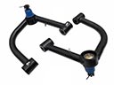
2009 Dodge Charger Knuckle, Front Driver Side Part Number: 4895711AB
Product Specifications- Other Name: Knuckle - Front; Steering Knuckle, Front Left; Knuckle Front
- Position: Front Driver Side
- Replaces: 4895711AA
- Item Weight: 20.70 Pounds
- Item Dimensions: 24.7 x 9.7 x 4.1 inches
- Condition: New
- Fitment Type: Direct Replacement
- SKU: 4895711AB
- Warranty: This genuine part is guaranteed by Mopar's factory warranty.
 Product Specifications
- Other Name: Knuckle - Front; Steering Knuckle, Front Right; Knuckle Front
- Position: Front Passenger Side
- Replaces: 4895710AA
- Item Weight: 20.70 Pounds
- Item Dimensions: 24.9 x 9.7 x 3.9 inches
- Condition: New
- Fitment Type: Direct Replacement
- SKU: 4895710AB
- Warranty: This genuine part is guaranteed by Mopar's factory warranty.
2009 Dodge Charger Steering Knuckle Parts and Q&A
- Q: How to Install a Steering Knuckle on 2009 Dodge Charger?A: The hub nut on the steering knuckle should always be replaced with a new one since the original can be used only once. Should a shield be used, attach it properly on your knuckle and secure it with 3 screws that are tightened to 10 Nm of force (89 in. lbs.). For hub and bearing installation, slide the hub and bearing onto the knuckle spindle, put the hub nut on and tighten it to 213 Nm (152 ft. lbs.). Make sure to install a new dust cap on top of the hub nut. When you attach the knuckle to the control arm, first measure the ball joint seal boot with a Digital micrometer. If it's found to be over 25.5 mm, release the air with some firm procedures: tip the stud, gently squeeze the boot, push the top of it down, center the stud and recheck the measurement. Cover the lower ball joint studs with the knuckle and tighten on new nuts just enough to hold them in place. Use a hex wrench along with a crow-foot wrench on a torque wrench to turn the new nut to 68 Nm + 90° (50 ft. lbs. + 90° turn) on the ball joint stud between the lower control arm and the knuckle. Do this process again to link another nut to the opposite side of the tension strut to the knuckle. Feed the upper ball joint stud into the knuckle and put on the nut, tightening it to 47 Nm + 90° turn (35 ft. lbs. + 90° turn). Place the outer tie rod stud through the knuckle, screw on the nut and tighten it to 85 Nm (63 ft. lbs.). Installing the disc brake caliper and adapter assembly comes after the brake rotor. Screw the brake flex hose routing bracket into the knuckle at 12 Nm (106 in. lbs.) and next install the wheel speed sensor head and tighten its mounting screw at 11 Nm (95 in. lbs.). Hook the wheel speed sensor cable and routing clip onto the brake flex hose bracket on the side. Assemble the tire and wheel, screwing in the nuts until they reach 150 Nm (110 ft. lbs.) in all models or 190 Nm (140 ft. lbs.) for police models. Lift the front of the vehicle slightly, push the brake pedal a few times to confirm firmness, check the brake fluid level in the tank and have your wheels aligned.
Related 2009 Dodge Charger Parts
 2009 Dodge Charger Control Arm
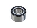 2009 Dodge Charger Wheel Bearing
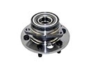 2009 Dodge Charger Wheel Hub
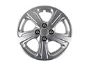 2009 Dodge Charger Wheel Cover
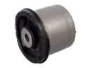 2009 Dodge Charger Axle Beam Mount
 2009 Dodge Charger Axle Pivot Bushing
 2009 Dodge Charger Axle Support Bushings
 2009 Dodge Charger Lateral Link
 2009 Dodge Charger Shock Absorber
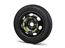 2009 Dodge Charger Spare Wheel
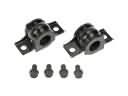 2009 Dodge Charger Sway Bar Bracket
 2009 Dodge Charger Sway Bar Bushing