JeepParts
My Garage
My Account
Cart
OEM Dodge Charger Differential Mount
- Select Vehicle by Model
- Select Vehicle by VIN
Select Vehicle by Model
orMake
Model
Year
Select Vehicle by VIN
For the most accurate results, select vehicle by your VIN (Vehicle Identification Number).
4 Differential Mounts found
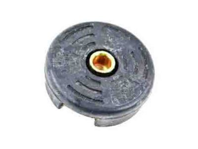
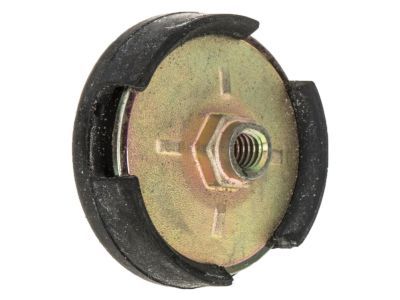
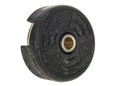
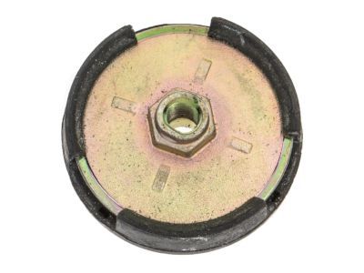
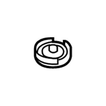
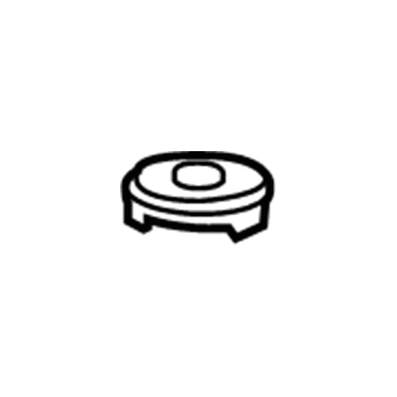
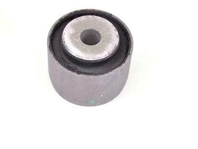
Dodge Charger Differential Mount, Rear Upper Part Number: 4578085AA
$86.08 MSRP: $128.83You Save: $42.75 (34%)Ships in 1-2 Business Days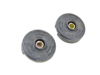
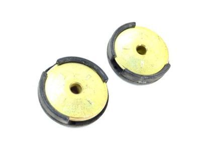
Dodge Charger Differential Mount, Rear Lower Part Number: 4578191AA
$22.70 MSRP: $33.65You Save: $10.95 (33%)Ships in 1-2 Business Days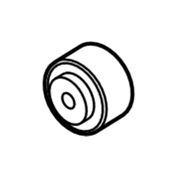
Dodge Charger Differential Mount, Rear Part Number: 68242689AA
$21.91 MSRP: $32.45You Save: $10.54 (33%)Ships in 1-2 Business Days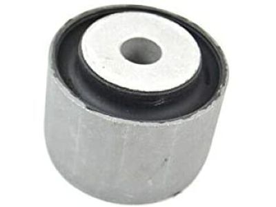
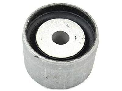
Dodge Charger Differential Mount, Rear Part Number: 4578084AC
Dodge Charger Differential Mount
Choose OEM Differential Mount that meet Dodge factory standards. Dodge designs and tests every component for precision and durability. Each Differential Mount follows strict manufacturing steps to lock in quality and fit. If your Dodge Charger matters to you, OEM parts make the smart choice. You'll get the exact look, feel, and performance you expect. Shop genuine Charger parts at the highly competitive prices online. Enjoy a manufacturer's warranty, a hassle-free return policy, and rapid delivery. No more guesswork with off brands. Get genuine parts with exact fit and true factory performance. Shop with confidence today at JeepPartsDeal.com.
Dodge Charger Differential Mount Parts and Q&A
- Q:How to install the Differential Mount on Dodge Charger?A:Inserting the tapered end of the new bushing into the crossmember bushing bore's forward end is the first step of the installation process. Ensure that the thrust bearing's hardened side faces the bolt head. The bolt, disc 9520-1, bushing, nut, washer, installer 9520-2 thrush bearing are to be assembled through crossmember and bushing. Into the end of the bushing, insert the installer and the disc into the opposite end of the crossmember bushing bore. With the nut held to prevent rotation, tighten the bolt to press the bushing into the crossmember until the installer bottoms against the bushing bore; remove the tools. Install the differential mounting bolt from the rear through the mount bushing, then raise the crossmember until the shocks pass through the pockets in the spring links but do not install the bolts yet. Use a jack to lift the crossmember until you can install but do not tighten the mounting bolts on the left side. Gradually lower the jack to permit the right side of the crossmember to drop just sufficiently for the coil spring installation. Also, check that the isolators are fully installed on the ends of the spring. Position the coil spring with isolators in the spring pocket and the top part aligned with the body mount. Next, jack up the axle, guiding the coil spring and lower end of the shock absorber into place. Stop when the lower mounting hole of the shock absorber aligns with the spring link. Without tightening, install the lower shock mounting bolt & nut. For all-wheel-drive vehicles, place spacers on top of the right crossmember mount bushings prior to raising the crossmember. Lift the right hand of the Crossmember into position and install the right hand mounting bolts, snuggling them but not tightening fully. Take off the left-side mounting bolts and slowly lower the jack to allow the left side of the crossmember to drop for the coil spring installation (insulators must be installed). Use the same procedure for the left side of the coil springs and then move the crossmember until the mounts are aligned with the location marks on the vehicle body. The distance between the tension link and weld flange must be at least 12 mm. Tighten all four crossmember mounting bolts to 180 Nm. Remove the jack and install the fuel filler tube. Clip the left rear wheel speed sensor cable to the routing clip. Pair and insert the left-hand rear wheel speed sensor connector into the body wiring harness connector, ensuring the retaining clip is secure. For standard or premium disc brakes, place the caliper guide pins into the caliper adapter and guide the caliper down through the rear suspension before inserting and tightening the guide pin bolts to 31 Nm and running the brake hose correctly. To install SRT8 disc brakes, support the spring link, slide the caliper with its pads over the brake rotor, fit the caliper mounting bolts, and tighten to 130 Nm. Above the rear crossmember, route the parking brake cable, connect the front parking brake cable, and install the routing bracket to the crossmember. Pull an axle half shaft through the hub and bearing and install the hub nut without tightening, and install the rear axle differential. With a helper applying the brakes, tighten the hub nut to 213 Nm and install the rear exhaust system. Next, install the tire and wheel assemblies and tighten the wheel mounting nuts to 150 Nm. After lowering the vehicle, connect the battery negative cable. Then, pump the brake pedal to ensure it is firm. Position the vehicle on an alignment rack. After that, tighten the nuts on the lower mounting bolt of both shock absorbers to 72 Nm. Finally, carry out a wheel alignment with particular attention to thrust angle.
- Q:How to service the Differential Mount on Dodge Charger?A:To service the differential mount, first disconnect and isolate the battery negative cable from the battery post, then raise and support the vehicle. Remove the wheel mounting nuts and tire and wheel assembly from each side of the rear. While a helper applies brakes to prevent hub rotation, remove the hub nut from the half shaft on each side. Next, remove the rear exhaust system and the rear axle differential, then slide each axle half shaft from the hub and bearing. Disconnect the front parking brake cable at the connector to the right rear parking brake cable above the axle differential, and remove the front parking brake cable from the equalizer. Remove the screw fastening the front parking brake cable routing bracket to the rear crossmember front flange. If equipped with standard or premium disc brakes, hold the guide pins from turning and remove the disc brake caliper guide pin bolts, then remove the brake caliper from the brake adapter and pads, guiding it up through the suspension and supporting it to avoid overextending the brake hose. For SRT8 disc brakes, place a trim stick between the brake pad and rotor edge, apply pressure to bottom the pistons in the caliper, support the spring link with a jack, and remove the caliper mounting bolts and the brake caliper with pads from the knuckle and rotor, hanging the assembly out of the way. Remove the wheel speed sensor connectors from the body wiring harness connector located in the luggage compartment floor pan, unclip the left wheel speed sensor cable from the routing clip, and remove the shock absorber lower mounting bolt and nut on each side of the vehicle. Mark the location of the rear crossmember on the body at all four mount locations, then support the forward end of the engine cradle with jack stands. Position a jack under the center of the rear crossmember, raise it to contact the crossmember, and secure it. Remove the fuel filler tube, then remove both front and rear mounting bolts fastening the crossmember in place, and slowly lower the crossmember to a comfortable working level. Remove the coil springs and isolators from the spring links, then remove the bolt from the bushing prior to removal. Before using Special Tool 9520, lubricate the bolt threads for ease of use. Assemble the necessary tools over the bushing, hold the nut from rotating, and tighten the bolt until the remover contacts the bushing and the receiver sets squarely against the crossmember. Continue tightening the bolt to press the bushing out of the crossmember, then remove the tools with the bushing.
Related Dodge Charger Parts
 Dodge Charger Lug Nuts
 Dodge Charger Wheel Bearing
 Dodge Charger Control Arm Bushing
 Dodge Charger Steering Knuckle
 Dodge Charger Axle Shaft Seal
 Dodge Charger Axle Vent
 Dodge Charger Bump Stop
 Dodge Charger Control Arm Shaft Kit
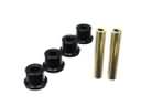 Dodge Charger Crossmember Bushing
 Dodge Charger Lateral Link
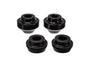 Dodge Charger Radius Arm Bushing
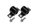 Dodge Charger Sway Bar Bushing