JeepParts
My Garage
My Account
Cart
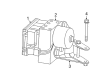
OEM Dodge Intrepid ABS Control Module
Anti Lock Brake Control Module- Select Vehicle by Model
- Select Vehicle by VIN
Select Vehicle by Model
orMake
Model
Year
Select Vehicle by VIN
For the most accurate results, select vehicle by your VIN (Vehicle Identification Number).
10 ABS Control Modules found


Dodge Intrepid Control Module Part Number: 4602253AB
$622.36 MSRP: $906.00You Save: $283.64 (32%)Ships in 1-3 Business Days


Dodge Intrepid Modulator Valve Part Number: 4897781AA
$1049.29 MSRP: $1330.17You Save: $280.88 (22%)Ships in 1-2 Business Days
Dodge Intrepid Modulator Valve Part Number: 5080684AA

Dodge Intrepid Control Module Part Number: 4759720

Dodge Intrepid Control Module Part Number: 4759326
Dodge Intrepid Control Module Part Number: 4605701

Dodge Intrepid Control Module Part Number: 5072309AA
Dodge Intrepid Control Module Part Number: 5093806AA
Dodge Intrepid Control Module Part Number: 5093809AA
Dodge Intrepid Control Module Part Number: 5080721AA
Dodge Intrepid ABS Control Module
Choose OEM ABS Control Module that meet Dodge factory standards. Dodge designs and tests every component for precision and durability. Each ABS Control Module follows strict manufacturing steps to lock in quality and fit. If your Dodge Intrepid matters to you, OEM parts make the smart choice. You'll get the exact look, feel, and performance you expect. Shop genuine Intrepid parts at the highly competitive prices online. Enjoy a manufacturer's warranty, a hassle-free return policy, and rapid delivery. No more guesswork with off brands. Get genuine parts with exact fit and true factory performance. Shop with confidence today at JeepPartsDeal.com.
Dodge Intrepid ABS Control Module Parts and Q&A
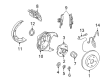
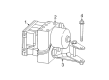
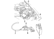
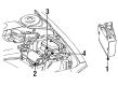
- Q: How to Service and Repair an ABS Control Module on Dodge Intrepid?A:The first thing to do is disconnect the remote ground cable from the ground stud on the right strut tower and protect it with a ground cable insulator and nut, to ensure it doesn't ground unintentionally. Put the brake pedal positioning tool on the floor, apply pressure to the brake pedal with your foot and let the pedal down past the first inch to flush the master cylinder reservoir. After that, remove the speed control servo bolt and nuts, unplug the wire harness connector and push the cable aside. Loose the screw holding the washer bottle filler neck, then take out the nut and bolt at the transmission controller and bracket, so you can lift the controller away from where it is mounted. Clean all areas of the Hcu and the brake tubes with Mopar6 Brake Parts Cleaner or a like product. Removal of the primary and secondary brake tubes from the master cylinder at the Hcu requires using a crow foot wrench and then remove the chassis brake tubes. Pull up on the lock to disconnect the 25-way wiring harness connector from the Cab. Lift the car, pull out the left front tire and wheel and remove all fasteners connecting the inner fender splash shield to the vehicle; then remove the 3 Icu mounting bolts and pull the Icu out through the side of the wheel well. Attach the vehicle's Icu, then cut the wires connected to the pump/motor to the Cab and use a socket wrench to remove the four bolts that secure the Cab to the Hcu, bringing separation. Attach the Cab to the Hcu and hold it there with four bolts secured to 2 Nm (17 inch lbs.) pressure. Following that, plug in the wiring harness for the pump/motor. After reinstating the Icu into the mounting bracket with 11 Nm of bolts, start the vehicle, place the inner fender splash shield back and install the tire and wheel after lowering the vehicle. Put the seal into the 25-way connector and then attach and lock the Cab cable there. Set in place the four wheel brake tubes and tighten them to 17 Nm (145 inch lbs.), then mount the primary and secondary Brake Lines from the master cylinder and secure each line to the same pressure of 17 Nm (145 inch lbs.). Drive in the transmission controller, screw in the washer bottle filler neck and mount the speed control servo. Take off the brake pedal tool and put the end of the remote cable on the left shock tower nut. Secure the cable by tightening the nut to 28 Nm (250 inch lbs.). As soon as the Icu has been installed, the Drbiii(R) scan tool should be used for initialization, bleeding is required for the base and Abs hydraulic systems and a road test should confirm the system's proper functionality.
- Q: How is the ABS Control Module Removed and Installed in Relation to the ICU and CAB on Dodge Intrepid?A:To remove the HCU you must remove the ICU from the vehicle and disassemble it. The HCU has to be attached to the CAB for its installation forming the ICU.


Related Dodge Intrepid Parts
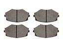 Dodge Intrepid Brake Pads
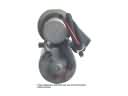 Dodge Intrepid ABS Pump And Motor Assembly
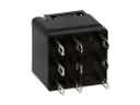 Dodge Intrepid ABS Relay
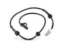 Dodge Intrepid ABS Sensor
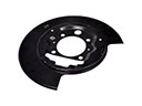 Dodge Intrepid Backing Plate
 Dodge Intrepid Brake Caliper
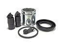 Dodge Intrepid Brake Caliper Repair Kit
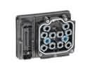 Dodge Intrepid Brake Controller
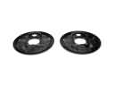 Dodge Intrepid Brake Dust Shields
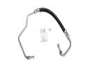 Dodge Intrepid Hydraulic Hose
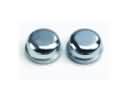 Dodge Intrepid Wheel Bearing Dust Cap
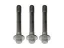 Dodge Intrepid Wheel Hub Bolt