JeepParts
My Garage
My Account
Cart
OEM 2003 Dodge Dakota A/C Clutch
Air Conditioning Clutch- Select Vehicle by Model
- Select Vehicle by VIN
Select Vehicle by Model
orMake
Model
Year
Select Vehicle by VIN
For the most accurate results, select vehicle by your VIN (Vehicle Identification Number).
2 A/C Clutches found


2003 Dodge Dakota Clutch & Pulley Part Number: 5083077AA
Product Specifications- Other Name: Clutch - A/C Compressor; A/C Compressor Clutch; Clutch Coil; Clutch; Clutch A/C Compressor
- Item Weight: 6.10 Pounds
- Item Dimensions: 6.8 x 6.8 x 2.5 inches
- Condition: New
- Fitment Type: Direct Replacement
- SKU: 5083077AA
- Warranty: This genuine part is guaranteed by Mopar's factory warranty.
2003 Dodge Dakota Clutch & Pulley Part Number: 5072658AA
Product Specifications- Other Name: Clutch - A/C Compressor; A/C Compressor Clutch; Clutch Coil; Clutch; Clutch A/C Compressor
- Item Weight: 6.10 Pounds
- Item Dimensions: 6.6 x 6.7 x 2.6 inches
- Condition: New
- Fitment Type: Direct Replacement
- SKU: 5072658AA
- Warranty: This genuine part is guaranteed by Mopar's factory warranty.
2003 Dodge Dakota A/C Clutch Parts and Q&A
- Q: How to Replace the A/C Clutch on 2003 Dodge Dakota?A: First, turn off the car, remove the negative cable from the battery and then take off the serpentine drive belt. Disconnect the wire harness at the clip that goes to the compressor clutch coil. With Special Tool 6462 from Kit 6460, push the two pins of the spanner wrench through the clutch plate's holes, secure the plate and get the hex nut out. Following that, take out the clutch plate and all the clutch shims and then use snap ring pliers to remove the snap ring on the outside of the front housing. Insert the lip of the rotor puller through the snap ring groove and then slide in the shaft protector (Special Tools C-6141-1 and C-6141-2 from Kit 6460). Place Special Tool C-6461 through the puller flange into the jaws of the rotor puller and secure by tightening. Turn clockwise on the puller center bolt until the rotor pulley can be removed. Open the screw and retainer on the clutch coil lead wire harness from the compressor's front housing, remove the snap ring from the compressor hub and free the clutch field coil. Examine the clamping surfaces between the clutch rotor and plate for excessive wear; replace them if there is any serious wear or marking. If oil is found on the shaft and nose part of the compressor when the surfaces are oily and the felt from the front cover is also oily, the shaft seal has sprung a leak and you must buy a new compressor. Test the clutch rotor bearing; if it's rough or there is too much grease leaking, replace both the rotor and the clutch plate. When installing, join the clutch field coil and snap ring and then use the compressor front housing screw to secure the clip and retain the wire lead of the clutch coil harness firmly. Place the rotor put together square against the compressor front housing hub, thread the handle (Special Tool 6464 from Kit 6460) into the driver (Special Tool 6143 from Kit 6460) and fit the driver assembly into the side of the rotor cartridge inside the bearing cavity, making sure it is resting on the inner race of the rotor bearing. When guiding the rotor, tap the driver at its end until it touches the hub of the compressor front housing and notice a different sound. Fit the front rotor snap ring to the beam with its bevel facing outward and ensure it's in the groove to keep the clutch from failing. Confirm sufficient space between the lead wire and clutch rotor and afterward zip-tie the original clutch shims to the compressor shaft. Place the shaft protector (Special Tool 6141-2 from Kit 6460) on the end, attach the clutch plate and tap the lock bolt until the clutch shims are touching it and listen. Turnthe compressor shaft hex nut until it reaches 15 to 20 Nm (11 to 15 ft. lbs.) torque. With a feeler gauge, measure the resulting air gap in the clutch. Put new shims in if it does not match the specification of 0.41 to 0.79 millimeter (0.016 to 0.031 inch) and lightly pry or tap to make the clutch consistent as you go around. Ensure you use the shims given with the clutch hardware package during installation.
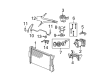
Related 2003 Dodge Dakota Parts
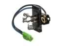 2003 Dodge Dakota Blower Motor Resistor
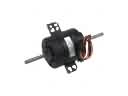 2003 Dodge Dakota Blower Motor
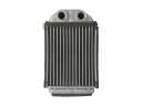 2003 Dodge Dakota Heater Core
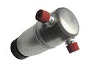 2003 Dodge Dakota A/C Accumulator
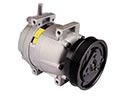 2003 Dodge Dakota A/C Compressor
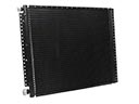 2003 Dodge Dakota A/C Condenser
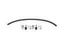 2003 Dodge Dakota A/C Hose
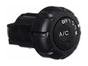 2003 Dodge Dakota A/C Switch
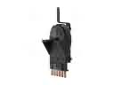 2003 Dodge Dakota Blower Control Switches
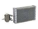 2003 Dodge Dakota Evaporator