JeepParts
My Garage
My Account
Cart
OEM 2004 Dodge Ram 2500 Camshaft
Cam- Select Vehicle by Model
- Select Vehicle by VIN
Select Vehicle by Model
orMake
Model
Year
Select Vehicle by VIN
For the most accurate results, select vehicle by your VIN (Vehicle Identification Number).
2 Camshafts found


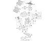
2004 Dodge Ram 2500 Camshaft Part Number: 53022064AA
$396.17 MSRP: $582.00You Save: $185.83 (32%)Product Specifications- Other Name: Camshaft - Engine; Camshaft Engine
- Replaces: 53021730BA, 53021730AC
- Item Weight: 13.80 Pounds
- Item Dimensions: 21.8 x 4.1 x 5.9 inches
- Condition: New
- Fitment Type: Direct Replacement
- SKU: 53022064AA
- Warranty: This genuine part is guaranteed by Mopar's factory warranty.

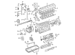
2004 Dodge Ram 2500 Camshaft Part Number: 5093139AB
Product Specifications- Other Name: Camshaft Includes Camshaft Gear; Camshaft Includes Camshaft Gear
- Item Weight: 27.00 Pounds
- Item Dimensions: 39.9 x 16.3 x 15.6 inches
- Condition: New
- Fitment Type: Direct Replacement
- SKU: 5093139AB
- Warranty: This genuine part is guaranteed by Mopar's factory warranty.
2004 Dodge Ram 2500 Camshaft Parts and Q&A
- Q: How to Remove and Replace a Camshaft on 2004 Dodge Ram 2500?A: Before you start, remove both negative battery cables and drain the A/C refrigerant if there is air conditioning. Take the vehicle on a hoist and pour the engine coolant into a fitting container. After lowering the vehicle, get rid of the radiator upper hose, viscous fan/drive assembly and fan shroud. Partially remove the hose from around the radiator filler neck and the radiator outlet and the hose from around the lower radiator. Unless equipped with a simple finger-release disconnect, use Special Tool 6931 to disconnect the transmission oil cooler lines from the radiator's front as directed in the Service Info for automatic transmission models. With the screws out, take out the radiator from the engine section and then remove the top radiator support panel. Should the vehicle have AC, unplug the A/C condenser refrigerant lines and plug the charge air cooler piping in where the original cooler inlet and outlet are, remove the mounting bolts and pull out the charge air cooler and the A/C condenser. Taking off the accessory drive belt and tensioner leads to removing the fan support/hub assembly, crankshaft damper and finally the speed indicator ring. Take out the securing bolts from the gear cover, gently remove the cover from the housing and pull the dust seal away with it. Take the Special Tool 7471-B Crankshaft Barring Tool and rotate the crankshaft until the timing marks on the two gears are aligned. Remove the cover on the cylinder head, rocker arms, cross heads and push rods and set up a system to mark them for reinstallation. You can remove the #5 and #6 cylinder intake and exhaust pushrods by pulling them through the holes in the cowl panel section with no rubber plugs in them. Acquire the tappet spacers in kit 8502 and use them to raise the tappets. Secure them with rubber bands to ensure they don't fall into the crankcase. Line up the camshaft timer marks with the crankshaft timing mark and then remove the bolts from the thrust plate and engine mount through bolts. Get engine support fixture special tool #8534 and steel bracket/wing nut special tool #8534A which you will need to raise the engine for removing the camshaft. Take out the camshaft, gear and thrust plate. Check for damage on the valve lobes and journals and measure the bearing journals along with the lobes; if the measurements are greater than permitted, replace the camshaft. Look for any extra wear in the camshaft bushing and holes using a telescoping bore gauge and micrometer and make sure the oil holes in the camshaft bushing are lined up with the cylinder block. Inspect the teeth and shaft of the camshaft gear for damage and replace the two together if they are cracked. Examine the camshaft thrust plate for any extra wear and compare the plate's thickness with the chart, changing anything that falls short of specs. Pour engine oil into the bores and bushing of the camshaft before putting in the camshaft, thrust plate and aligning the timing marks. Fit the heels of the thrust plate, tighten them to 24 Nm, measure camshaft backlash and end clearance and subsequently remove the wooden dowel rods and rubber bands from the tappets. Place engine oil on the push rods and then fix them securely in their original places, where they align with the valve tappets. Apply oil to the valve tips and then install the crossheads, rocker arms and pedestals with 36 Nm (27 ft. lbs.) torque. Perform valve lash adjustment, then mount the cylinder head cover using a reusable gasket, the gear housing and a front crankshaft dust seal. First, set up the crankshaft damper with the speed indicator ring, then assemble the support/hub for the fan, secure the bolts with a 33 Nm torque rating. Put on the power steering pump, torque on the accessory drive belt tensioner to 43 Nm (43 ft. lbs.) and fasten on the accessory drive belt. Install or fit the charge air cooler and any additional parts, use a torque wrench to tighten the mounting bolts to 2 Nm (17 in. lbs.) and join the pipes for the charge air cooler, again using the torque wrench on the clamps. Produce the radiator upper support panel, tighten the petcock shut, ease the radiator down into place below the hood and secure the mounting bolts with 11 Nm (95 in. lbs.) torque. Lift the engine, join the radiator lower hose to its port and put the clamp on and then connect the transmission auxiliary oil cooler lines if available. Lower your vehicle on your engine hoist, fit the fan shroud in place, tighten the shroud mounting screws to 6 Nm and connect the electronically controlled fan/drive assembly by connecting its harness connector. Fit the coolant recovery and windshield washer fluid reservoirs onto the fan shroud, attach the recovery hose to the radiator filler neck, add engine coolant, charge the A/C system with refrigerant if possible, link up the battery's negative wires and start the engine.
Related 2004 Dodge Ram 2500 Parts
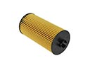 2004 Dodge Ram 2500 Oil Filter
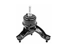 2004 Dodge Ram 2500 Transmission Mount
 2004 Dodge Ram 2500 Rod Bearing
 2004 Dodge Ram 2500 Camshaft Seal
 2004 Dodge Ram 2500 Crankshaft
 2004 Dodge Ram 2500 Crankshaft Seal
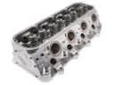 2004 Dodge Ram 2500 Cylinder Head
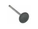 2004 Dodge Ram 2500 Intake Valve
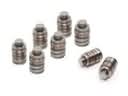 2004 Dodge Ram 2500 Lash Adjuster
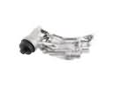 2004 Dodge Ram 2500 Oil Filter Housing
 2004 Dodge Ram 2500 Rocker Arm
 2004 Dodge Ram 2500 Timing Cover Gasket