JeepParts
My Garage
My Account
Cart
OEM 2006 Jeep Commander Drive Shaft
Axle Shaft- Select Vehicle by Model
- Select Vehicle by VIN
Select Vehicle by Model
orMake
Model
Year
Select Vehicle by VIN
For the most accurate results, select vehicle by your VIN (Vehicle Identification Number).
7 Drive Shafts found


2006 Jeep Commander Drive Shaft Part Number: 52853004AF
$914.21 MSRP: $1410.00You Save: $495.79 (36%)Ships in 1-2 Business DaysProduct Specifications- Other Name: Shaft - Drive; Driveshaft; Shaft Drive Rear 1-Piece
- Replaces: 52853004AE, 52853004AC, 52853004AD
- Item Weight: 23.10 Pounds
- Item Dimensions: 53.0 x 8.4 x 6.1 inches
- Condition: New
- Fitment Type: Direct Replacement
- SKU: 52853004AF
- Warranty: This genuine part is guaranteed by Mopar's factory warranty.


2006 Jeep Commander Drive Shaft Part Number: 52105728AE
$1230.88 MSRP: $1815.00You Save: $584.12 (33%)Ships in 1-3 Business DaysProduct Specifications- Other Name: Shaft - Drive; Driveshaft
- Replaces: 52105728AD
- Item Weight: 19.30 Pounds
- Item Dimensions: 41.3 x 6.9 x 5.7 inches
- Condition: New
- Fitment Type: Direct Replacement
- SKU: 52105728AE
- Warranty: This genuine part is guaranteed by Mopar's factory warranty.


2006 Jeep Commander Drive Shaft Part Number: 52105760AF
Product Specifications- Other Name: Shaft - Drive; Driveshaft; Shaft Drive Rear 1-Piece
- Replaces: 52105760AE, RL105760AF, 52105760AD, 52105760AC
- Item Weight: 18.70 Pounds
- Item Dimensions: 46.2 x 8.2 x 7.1 inches
- Condition: New
- Fitment Type: Direct Replacement
- SKU: 52105760AF
- Warranty: This genuine part is guaranteed by Mopar's factory warranty.


2006 Jeep Commander Drive Shaft Part Number: 52853431AA
Product Specifications- Other Name: Shaft - Drive; Driveshaft; Shaft Drive Front
- Item Weight: 19.00 Pounds
- Item Dimensions: 41.6 x 6.2 x 6.0 inches
- Condition: New
- Fitment Type: Direct Replacement
- SKU: 52853431AA
- Warranty: This genuine part is guaranteed by Mopar's factory warranty.
2006 Jeep Commander Drive Shaft Part Number: 52853006AF
Product Specifications- Other Name: Shaft - Drive; Driveshaft; Shaft Drive Rear 1-Piece
- Replaces: 52853006AC, 52853006AE, 52853006AD
- Item Weight: 20.30 Pounds
- Item Dimensions: 21.2 x 10.0 x 9.2 inches
- Condition: New
- Fitment Type: Direct Replacement
- SKU: 52853006AF
- Warranty: This genuine part is guaranteed by Mopar's factory warranty.

2006 Jeep Commander Drive Shaft Part Number: 52853433AB
Product Specifications- Other Name: Shaft - Drive; Driveshaft; Shaft Drive Rear 1-Piece
- Item Weight: 18.70 Pounds
- Item Dimensions: 49.4 x 7.4 x 7.2 inches
- Condition: New
- Fitment Type: Direct Replacement
- SKU: 52853433AB
- Warranty: This genuine part is guaranteed by Mopar's factory warranty.
2006 Jeep Commander Drive Shaft Part Number: 52105726AF
Product Specifications- Other Name: Shaft - Drive; Driveshaft; Shaft Drive Rear 1-Piece
- Replaces: 52105726AD, 52105726AE, 52105726AC
- Item Weight: 21.10 Pounds
- Item Dimensions: 54.1 x 11.2 x 9.2 inches
- Condition: New
- Fitment Type: Direct Replacement
- SKU: 52105726AF
- Warranty: This genuine part is guaranteed by Mopar's factory warranty.
2006 Jeep Commander Drive Shaft Parts and Q&A
- Q: How to Measure the Front and Rear Output Angles on a Drive Shaft on 2006 Jeep Commander?A: For measuring the front (output) angle on a C/V front propeller shaft, set Inclinometer 7663 on the flange ring and for the propeller shaft angle, apply the inclinometer to the shaft tube. Take measurements for the rear (output) angle while staying with the transfer case/transmission flange. First, lift each axle as level as you can to let the wheels and propeller shaft rotate. If you have universal joint snap rings, detach them so the base will sit evenly and smoothly on the traction rack. Position the vehicle so the output yoke bearing cap is toward the ground. Do this starting from front to back and always on only one side of the vehicle, then take your measurements. Use the inclinometer to measure the angle of the yoke bearing cap or pinion flange ring, point it parallel to the shaft, center the bubble in the sight glass and make a note of the result to get the transmission or output yoke angle. Then, turn the propeller shaft 90 degrees and put the inclinometer on the yoke bearing cap or propeller shaft tube, parallel to the rotation. Adjust the bubble in the center and record the measurement which can also be done at the rear end of the shaft for the propeller shaft angle. The difference between the larger and smaller figure (C - A) gives you the transmission output angle. To measure the pinion shaft angle, rotate the propeller shaft again, put the inclinometer on the pinion yoke bearing cap facing the shaft and center the bubble to determine the angle shown on the scale. After that, take the larger figure away from the smaller (C minus B) to determine the axle Input Operating Angle. Good cancellation means that the operating angles of the U-joint system are within 3 degrees and those of the constant velocity joint are within 10 degrees, while a continuous operating angle for the propeller shaft is at least 1/2 of 1 degree.
Related 2006 Jeep Commander Parts
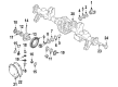
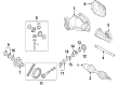
 2006 Jeep Commander Differential
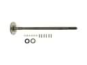 2006 Jeep Commander Axle Shaft
 2006 Jeep Commander Carrier Bearing Spacer
 2006 Jeep Commander CV Boot
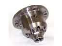
 2006 Jeep Commander CV Joint Companion Flange
 2006 Jeep Commander Differential Bearing
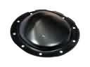 2006 Jeep Commander Differential Cover
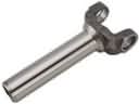 2006 Jeep Commander Driveshaft Yokes
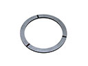 2006 Jeep Commander Mainshaft Washer
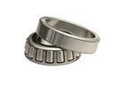 2006 Jeep Commander Pinion Bearing
 2006 Jeep Commander Pinion Washer
 2006 Jeep Commander Transfer Case Seal