JeepParts
My Garage
My Account
Cart
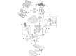
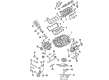
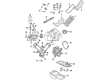
OEM 2006 Jeep Commander Exhaust Valve
Exhaust Muffler Valve- Select Vehicle by Model
- Select Vehicle by VIN
Select Vehicle by Model
orMake
Model
Year
Select Vehicle by VIN
For the most accurate results, select vehicle by your VIN (Vehicle Identification Number).
3 Exhaust Valves found


2006 Jeep Commander Exhaust Valve Part Number: 53021551AB
$34.28 MSRP: $49.45You Save: $15.17 (31%)Ships in 1-2 Business DaysProduct Specifications- Other Name: Valve - Exhaust; Valve Exhaust Standard
- Item Weight: 0.60 Pounds
- Item Dimensions: 5.4 x 1.8 x 1.8 inches
- Condition: New
- Fitment Type: Direct Replacement
- SKU: 53021551AB
- Warranty: This genuine part is guaranteed by Mopar's factory warranty.

2006 Jeep Commander Exhaust Valve Part Number: 53021916AB
$37.89 MSRP: $47.85You Save: $9.96 (21%)Ships in 1-2 Business DaysProduct Specifications- Other Name: Valve - Exhaust; Valve Springs; Valves; Valve Exhaust Standard
- Replaces: 53021644AB
- Item Weight: 0.60 Pounds
- Condition: New
- Fitment Type: Direct Replacement
- Require Quantity: 3
- SKU: 53021916AB
- Warranty: This genuine part is guaranteed by Mopar's factory warranty.


2006 Jeep Commander Exhaust Valve Part Number: 53020748
Product Specifications- Other Name: Valve - Exhaust; Intake Valve; Valves; Valve Exhaust Standard
- Item Weight: 1.10 Pounds
- Item Dimensions: 9.5 x 5.2 x 1.9 inches
- Condition: New
- Fitment Type: Direct Replacement
- SKU: 53020748
- Warranty: This genuine part is guaranteed by Mopar's factory warranty.
2006 Jeep Commander Exhaust Valve Parts and Q&A
- Q: How to Service and Repair Exhaust Valves and Intake Valves on 2006 Jeep Commander?A: Before you service or repair the valves on the intake and exhaust, take off the cylinder heads. Initially, you should remove the rocker arms and lash adjusters, then continue with the camshaft bearing caps and camshaft. Apply Tool C-3422-B or C-3422-C Valve Spring Compressor together with the Tool 8519 Adapter to widen the spring, tapping the top of the spring if the spring retainer locks are too tight. Be careful when pulling out the spring retainer lock halves since the valve spring will be under tension when releasing the compressor. After that, take away the valve spring compressor, spring retainer and valve spring, remove burrs from the valve stem and check the keeper grooves for sharp edges before you remove the valve from the cylinder head. Take out the valve stem seal and make a mark on the valve for installation. Always check and test the valve springs before using them again when valves are being removed. Test the shape of the springs, ensuring they are not damaged. Then, measure the spring load using Tool C-647 and change out springs that do not comply with the standards. Prior to installation, oil the valve stem with clean engine oil and push it into the cylinder head hole, making sure the valve stem seal is completely in place. After that, put on the spring and spring retainer, press the spring down with the compressor and fit both halves of the retainer into place. Loosening the compressor, check that both retainer halves and the spring retainer are in position. Cover the camshaft journal with clean oil, line up the sprocket dowels of both the left and right camshafts at 11:00 and 12:00 o'clock respectively and place the bearing covers. After fitting the camshaft bearing cap retaining bolts, tighten them to 11 Nm (100 inch lbs.), by turning them in the correct sequence. Later, fix the hydraulic lash adjusters and rocker arms.
Related 2006 Jeep Commander Parts
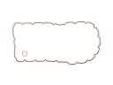 2006 Jeep Commander Oil Pan Gasket
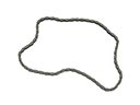 2006 Jeep Commander Timing Chain
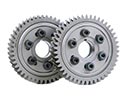 2006 Jeep Commander Cam Gear
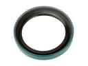 2006 Jeep Commander Crankshaft Seal
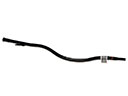 2006 Jeep Commander Dipstick Tube
 2006 Jeep Commander Engine Cover
 2006 Jeep Commander Engine Mount
 2006 Jeep Commander Lash Adjuster
 2006 Jeep Commander Oil Pump
 2006 Jeep Commander Rod Bearing
 2006 Jeep Commander Timing Cover Gasket
 2006 Jeep Commander Valve Stem Seal