JeepParts
My Garage
My Account
Cart
OEM 2008 Chrysler Aspen Instrument Cluster
Speedometer Instrument Cluster- Select Vehicle by Model
- Select Vehicle by VIN
Select Vehicle by Model
orMake
Model
Year
Select Vehicle by VIN
For the most accurate results, select vehicle by your VIN (Vehicle Identification Number).
2 Instrument Clusters found

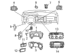
2008 Chrysler Aspen Instrument Cluster Part Number: 68028113AC
Product Specifications- Other Name: Cluster - Instrument Panel; Cluster Assembly
- Item Weight: 3.30 Pounds
- Item Dimensions: 16.8 x 10.2 x 6.3 inches
- Condition: New
- Fitment Type: Direct Replacement
- SKU: 68028113AC
- Warranty: This genuine part is guaranteed by Mopar's factory warranty.

2008 Chrysler Aspen Lens Part Number: 68003678AA
Product Specifications- Other Name: Lens - Instrument Cluster; Instrument Panel Lens; Mask And Lens Instrument Cluster
- Item Weight: 2.20 Pounds
- Condition: New
- Fitment Type: Direct Replacement
- SKU: 68003678AA
- Warranty: This genuine part is guaranteed by Mopar's factory warranty.
2008 Chrysler Aspen Instrument Cluster Parts and Q&A
- Q: How to Install the Instrument Cluster Assembly on 2008 Chrysler Aspen?A: The first step to install the instrument panel assembly is to turn off the supplemental restraint system by disconnecting the battery negative cable and waiting two minutes for the system to drain via the capacitor. Make sure the occupant restraint controller is okay by not allowing any damage to it from bumps or shakes. Lower the instrument panel assembly into the vehicle at the driver's side and set it onto the side support pins. Tighten the four fence line bolts until they reach 8 Nm. Connect the electrical input on the sensor, attach the instrument panel defroster grille and make sure it is all the way in. Place the trim panel on the passenger side A-pillar and attach it with bolts, torque of 6 Nm. Put in the passenger side rear floor duct, secure the ground wire and harness with their screws and tighten the harness and ground wire bolts to 14 Nm. Attach the amplifier and antenna electrical cords, install the amplifier and tighten the bolts to 6 Nm. Place the trim cover on the cowl, on the doorsill and on the passenger side bolts, ensuring each is tightened using 27 Nm. Set in place the panel end cap, use the support bolts for the driver's side and insert the driver's side floor duct. Attach the driver's seat, tighten the center support bolts to 11 Nm and put the center instrument panel wiring harness down under the carpet. Prior to putting the ORC connectors into the receptacles, make sure the lever arms are not engaged on the wire harness. After connecting the driver connectors to the ORC, be sure to push the latch fully into place on every connector. Fit the floor console, put the driver's side A-pillar trim in place and slot the retaining clips into their holes. Put in the bolts and tighten them to 6 Nm, afterwards add the ground wire and tighten the bolts go 14 Nm. Join the electrical cables at the fuse block, attach the brake release rod to the pedal assembly arm and screw in the support bolts with 14 Nm torque. Set the steering column over the support in the dash and loosely secure it with the nuts. Move the steering column up with the help of the studs, then snug each nut manually. Put the steering shaft coupler onto the steering shaft and put the new bolt in place loosely. Install the steering column in the opening of the dash, then fasten the nuts using 28 Nm of torque as suggested by the book. Adjust the coupler bolt to 38 Nm, put in a new brake light switch, install the shifter cable and tie the wiring harness to the steering column. Put in the SKIM module along with the upper and lower column shrouds and screws. Insert the column tilt lever, add fasteners for the steering column opening reinforcement, insert guide screws for the hood release handle and attach the steering column opening cover with two screws. Finally, put in the left instrument panel end cap, left cowl trim cover and left door sill trim cover making sure they sit properly. Only reattach the negative battery cable when the supplemental restraint system verification test has been carried out after any work on these parts.
Related 2008 Chrysler Aspen Parts
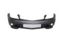 2008 Chrysler Aspen Bumper
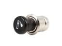 2008 Chrysler Aspen Cigarette Lighter
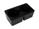 2008 Chrysler Aspen Cup Holder
 2008 Chrysler Aspen Door Lock Actuator
 2008 Chrysler Aspen Glove Box
 2008 Chrysler Aspen Seat Cover
 2008 Chrysler Aspen Seat Cushion
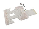 2008 Chrysler Aspen Seat Heater
 2008 Chrysler Aspen Seat Switch
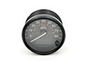 2008 Chrysler Aspen Speedometer
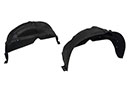 2008 Chrysler Aspen Wheelhouse
 2008 Chrysler Aspen Windshield Washer Nozzle