JeepParts
My Garage
My Account
Cart
OEM Chrysler Aspen Instrument Cluster
Speedometer Instrument Cluster- Select Vehicle by Model
- Select Vehicle by VIN
Select Vehicle by Model
orMake
Model
Year
Select Vehicle by VIN
For the most accurate results, select vehicle by your VIN (Vehicle Identification Number).
5 Instrument Clusters found

Chrysler Aspen Instrument Cluster Part Number: 5172006AI
Chrysler Aspen Instrument Cluster Part Number: 68028113AC

Chrysler Aspen Lens Part Number: 68003678AA

Chrysler Aspen Instrument Cluster Part Number: 68039994AE
Chrysler Aspen Instrument Cluster Part Number: 68039990AE
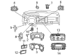
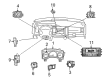
Chrysler Aspen Instrument Cluster
Choose OEM Instrument Cluster that meet Chrysler factory standards. Chrysler designs and tests every component for precision and durability. Each Instrument Cluster follows strict manufacturing steps to lock in quality and fit. If your Chrysler Aspen matters to you, OEM parts make the smart choice. You'll get the exact look, feel, and performance you expect. Shop genuine Aspen parts at the highly competitive prices online. Enjoy a manufacturer's warranty, a hassle-free return policy, and rapid delivery. No more guesswork with off brands. Get genuine parts with exact fit and true factory performance. Shop with confidence today at JeepPartsDeal.com.
Chrysler Aspen Instrument Cluster is one of the most significant parts that improve the driver's satisfaction and provide valuable data concerning the car performance and road conditions. A vehicle's Instrument Cluster is speedometer, tachometer, and fuel gauge that is reliable and performs well placed at the back of the steering wheel with several lights and symbols. The design depicted above guarantees that the Chrysler Aspen needs to update its drivers about certain important measures, so their performance both on the road and in terms of efficiency is improved. Over the years, the Instrument Cluster has been different starting with very basic design and moving to advanced technologies and digital tools with increased efficiency and better usability by Chrysler. Best suited for the Chrysler Aspen models, the Instrument Cluster has a major importance in keeping the driver informed for safe operation of the vehicle. First of all, it is important to note that one of the best embodiments of the Chrysler Group's strategy is the Chrysler Aspen HEV hybrid model, characterized by the presence of a unique Instrument Cluster that not only provides the driver with information that would help him/her extract the top level of fuel efficiency from the vehicle, but also ensures that at low speeds, the Chrysler Aspen HEV hybrid model will function in electric mode only, thereby underlining its importance As a result of the Chrysler Aspen Instrument Cluster, which has a touch screen available navigation system as well as premium audio, buyers gain full reassurance of the company's commitment to quality and performance on every trip Chrysler takes.
Chrysler Aspen Instrument Cluster Parts and Q&A
- Q: How to Install the Instrument Cluster and Ensure Proper Handling of the Supplemental Restraint System on Chrysler Aspen?A:Before installing the instrument panel, disconnect the battery negative cable to switch off the Supplemental Restraint System and let the system capacitor discharge for two minutes. Attach the instrument panel assembly through the driver's side door and fit it onto the side support pins. Attach it to the pole with four fenceline bolts each tightened to 8 Nm. Carefully insert the sensor electrical connector, insert the instrument panel defroster grille and mount the passenger side A-pillar trim panel with bolts fastened at 6 Nm. Put in the passenger side rear floor duct, attach the passenger side wire harness and ground wire before tightening their bolts to 14 Nm. Join the amplifier and antenna electrical plugs, fit the amplifier into place and fasten the bolts to 6 Nm. Choose the right trim for the cowl, close door sill and support bolts by the left side bolster rivet. Install the suitable instrument panel end cap, tighten the driver's side bolts to 27 Nm and attach the driver's side floor duct. Fix the driver's seat into place, tighten the center support bolts to a torque of 11 Nm and attach the center instrument panel wiring harness below the carpet using bolts. Release the lever arm of each connector for the Occupant Restraint Controller (ORC) before you insert them into their slots. Join up all wire harness connectors with the ORC and confirm that each latch snaps fully into place. Connect the floor panel under the footwell, position and install the driver's side A-pillar trim and screw it in place with bolts tightened to 6 Nm. Place the ground wire and make sure the bolts are tightened to 14 Nm. Connect the electrical connectors at the fuse block, connect the brake release rod to the assembly on the pedal and tightly install the bolts to 14 Nm on the pedal support. Slide the Steering Column onto the dash panel support and secure the mounting nuts only slightly. Move the steering until it's against the studs and use a wrench to tighten the connecting nuts by hand. Slide the steering shaft coupler over the steering shaft and fasten a new bolt temporarily. Place the steering column in line with the steering column component and tighten the locking bolts beginning with the one above and to the left, up to 28 Nm. Secure the coupler bolt at 38 Nm, set up a new Brake Light Switch, fit the shifter cable and further attach the wiring harness to the column. Install each component separately using its correct screws: the SKIM module, both shrouds for the columns, the column tilt lever, hood release handle, steering column opening reinforcement and the steering column opening cover. Finally, set the left instrument panel end cap, the left cowl trim cover and the left door sill trim cover, holding them in place with the installed screw. Ensure the supplemental restraint system verification test is performed after you work on any supplemental restraint system part before placing the negative terminals together.
- Q: How to Remove the Instrument Cluster on Chrysler Aspen?A:To start, block the supplemental restraint system by cutting power to the battery, then wait two minutes so that the system's capacitor can discharge. Remember not to hit or let go of the occupant restraint controller, because this may harm the impact sensor. Change one part at a time and perform the supplemental restraint verification every time after changing an occupied seat restraint assembly. Open by taking off the left door sill trim, the left cowl trim and the left instrument panel end cap using a suitable tool from the Tengine system. Loosen and take out the screws to open the Steering Column and pull back the hood release handle. Take out the reinforcement behind the steering column and the steering column tilt lever and then remove the upper and lower column shrouds. Detach the wiring harness connectors from the column and free the Shift Cable at the actuator from its bracket. Separate the electrical connector of the SKIM module and undo the steering shaft coupler bolt above. Then slide the shaft away from the steering gearbox. Disconnect and toss out the Brake Light Switch and undo the four nuts that secure the steering column on the mounts; next, pull the steering column from the studs at its base. Take out the steering wheel assembly, loosen the bolts holding the pedal support bracket in place and detach the release rod from the pedal assembly. Take out the electrical connectors from the fuse block, unscrew the ground wire and take off the A-pillar trim after removing the bolts from both the driver's side A-pillar grab handle covers. Take out the console beneath the driver's feet and unhook the body wire harnesses from the ORC. Take the carpet out of the way so you can access the center harness screws and pull the instrument panel wiring harness up from the carpet area. Undo the center bolts, take out the driver's seat and unbolt the supports on the floor. Then remove the ducts from the driver's side and take off the instrument panel end cap on the right. Take out the passenger side support bolts, right door sill trim cover and right cowl trim cover. Get rid of the amplifier, its electrical connectors, then get rid of the bolts that hold the harness and ground wire. Take out the rear floor duct on the passenger side, the A-pillar trim panel and the instrument panel defroster grille. If the vehicle has a sensor connector, pull it off, then loosen the four fenceline bolts and lift the panel off its mounts near the driver's door.


Related Chrysler Aspen Parts
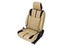 Chrysler Aspen Seat Covers
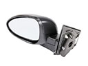 Chrysler Aspen Car Mirror
 Chrysler Aspen Center Console
 Chrysler Aspen Cigarette Lighter
 Chrysler Aspen Cup Holder
 Chrysler Aspen Liftgate Lock Actuator
 Chrysler Aspen Seat Cushion
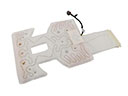 Chrysler Aspen Seat Heater
 Chrysler Aspen Seat Switch
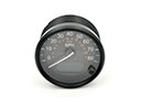 Chrysler Aspen Speedometer
 Chrysler Aspen Sunroof
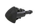 Chrysler Aspen Windshield Washer Nozzle