JeepParts
My Garage
My Account
Cart
OEM Chrysler Cirrus A/C Clutch
Air Conditioning Clutch- Select Vehicle by Model
- Select Vehicle by VIN
Select Vehicle by Model
orMake
Model
Year
Select Vehicle by VIN
For the most accurate results, select vehicle by your VIN (Vehicle Identification Number).
1 A/C Clutch found

Chrysler Cirrus Clutch Part Number: 4762849
Chrysler Cirrus A/C Clutch
Choose OEM A/C Clutch that meet Chrysler factory standards. Chrysler designs and tests every component for precision and durability. Each A/C Clutch follows strict manufacturing steps to lock in quality and fit. If your Chrysler Cirrus matters to you, OEM parts make the smart choice. You'll get the exact look, feel, and performance you expect. Shop genuine Cirrus parts at the highly competitive prices online. Enjoy a manufacturer's warranty, a hassle-free return policy, and rapid delivery. No more guesswork with off brands. Get genuine parts with exact fit and true factory performance. Shop with confidence today at JeepPartsDeal.com.
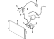
The Chrysler Cirrus A/C Clutch plays an integral role in the Chrysler Cirrus automobiles' air conditioning system and has received positive reviews on the same from users. This A/C Clutch effectively transmits and unlocks energy from the engine to the A/C compressor as soon as air conditioning is 'on'. Chrysler Cirrus A/C Clutch utilizes the belt drive that has a drum as the magnet to provide the much-needed traction thus enabling the compressor to work as expected. When not in use, it can swivel, and this lessens stress on the engine, and totally boosts the efficiency. Chrysler Cirrus A/C Clutch fits different models of Chrysler Cirrus and helps the drivers to control the cabin climate regardless the certain type of the car. It can play a part in increasing safety as a properly working A/C system helps a driver to be more comfortable and thus more alert, especially when driving in hot climate. Notably, the Chrysler Cirrus A/C Clutch is created with the anticipation of problems such as slipping or sticking, which in turn hampers and weakens an automobiles cooling processing, and thus increase fuel usage. This mostly involves checking up on the A/C Clutch frequently and making sure that it is replaced in good time. Thus, the Chrysler Cirrus A/C Clutch may be viewed as one of the most valuable additions to the atmosphere of the Chrysler Cirrus remarkably providing its owners with reliability and power.
Chrysler Cirrus A/C Clutch Parts and Q&A
- Q: How to Service and Repair an A/C Clutch on Chrysler Cirrus?A:To begin, disconnect and separate the negative battery cable and after that, get rid of the serpentine Drive Belt. Remove the connector for the compressor clutch coil wire harness and then unscrew the four bolts that hold the compressor to its mounting bracket. After that, take the compressor out, holding it in the engine compartment while you work. Through the clutch plate holes, fit both pins into place with Special Tool C-4489, then rotate the stationary clutch plate to loosen and remove the hex nut. Use Special Tool C-6461 to unfasten the clutch plate after that, then extract the compressor shaft key and the clutch shims. Snap the external front housing snap ring off, slide the tool C-6141-1 lip into the proper groove and insert the shaft protector (C-6141-2). Insert the special Tool C-6461 through the puller flange into the jaws and tighten them both clockwise until you can free the rotor pulley. The screw and retainer should be taken off the clutch coil lead wire harness on the compressor front housing. Then remove the snap ring from the compressor hub and unhook the clutch field coil. Examine the wear on the clutch friction surfaces by checking both the pulley and front plate. If either is damaged, replace them. See if there is oil at the front cover, shaft and nose end of the compressor; a wet front cover felt tells you the shaft seal is broken and the unit should be replaced. Look for roughness and unnecessary grease from the clutch pulley bearing; if either is found, replace it. First, attach the clutch field coil and the snap ring so that the clutch coil lead wire harness retaining clip can be added next, secured to the compressor front housing by a retaining screw. Place the rotor assembly squarely over the front compressor housing hub, attach the pulley bearing assembly using Special Tool C-6871, install the installer on the shaft and turn the nut until the assembly is set correctly. Fit the front snap ring pliers on the snap ring, with the bevel side facing away from the dowel and press it to be sure it is in place. Put the compressor shaft key and original clutch shims onto the shaft, then fit the clutch plate using Special Tool C-6463 and tighten the hex nut to 14.4 Nm (10.5 ft. lbs.) Using a feeler gauge, make sure the clutch is slightly below or equal to 0.79 millimeters (0.031 inch). When there's an uneven air gap, lift the hinge slightly at the smaller areas and press it down harder in the wider areas. When the installation is finished, set the heater-A/C control to Recirculation Mode, the blower motor switch to its highest speed and begin cycling the compressor clutch twenty times (five seconds on and five seconds off) at engine speeds of 1500 to 2000 rpm to improve compressor clutch performance.

Related Chrysler Cirrus Parts
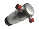 Chrysler Cirrus A/C Accumulator
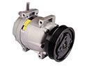 Chrysler Cirrus A/C Compressor
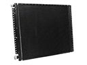 Chrysler Cirrus A/C Condenser
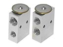 Chrysler Cirrus A/C Expansion Valve
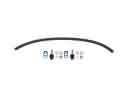 Chrysler Cirrus A/C Hose
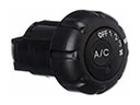 Chrysler Cirrus A/C Switch
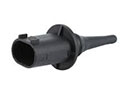 Chrysler Cirrus Ambient Temperature Sensor
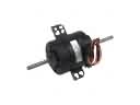 Chrysler Cirrus Blower Motor
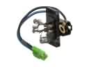 Chrysler Cirrus Blower Motor Resistor
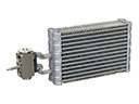 Chrysler Cirrus Evaporator
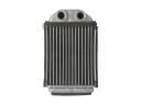 Chrysler Cirrus Heater Core