JeepParts
My Garage
My Account
Cart
OEM Chrysler LHS Steering Knuckle
Front Steering Knuckle- Select Vehicle by Model
- Select Vehicle by VIN
Select Vehicle by Model
orMake
Model
Year
Select Vehicle by VIN
For the most accurate results, select vehicle by your VIN (Vehicle Identification Number).
8 Steering Knuckles found

Chrysler LHS Knuckle, Front Passenger Side Part Number: 4782124AB
$311.58 MSRP: $459.00You Save: $147.42 (33%)
Chrysler LHS Knuckle Part Number: 4755059
$100.15 MSRP: $126.96You Save: $26.81 (22%)Ships in 1-2 Business Days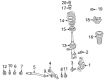
Chrysler LHS Knuckle, Front Passenger Side Part Number: 4782004AB
$333.14 MSRP: $422.32You Save: $89.18 (22%)Ships in 1-2 Business DaysChrysler LHS Knuckle, Front Driver Side Part Number: 4782005AB

Chrysler LHS Steering Knuckle Part Number: 4755058
Chrysler LHS Knuckle, Front Passenger Side Part Number: 4782124AC
Chrysler LHS Knuckle, Front Driver Side Part Number: 4782125AC
Chrysler LHS Knuckle, Front Driver Side Part Number: 4782125AB
Chrysler LHS Steering Knuckle
Choose OEM Steering Knuckle that meet Chrysler factory standards. Chrysler designs and tests every component for precision and durability. Each Steering Knuckle follows strict manufacturing steps to lock in quality and fit. If your Chrysler LHS matters to you, OEM parts make the smart choice. You'll get the exact look, feel, and performance you expect. Shop genuine LHS parts at the highly competitive prices online. Enjoy a manufacturer's warranty, a hassle-free return policy, and rapid delivery. No more guesswork with off brands. Get genuine parts with exact fit and true factory performance. Shop with confidence today at JeepPartsDeal.com.
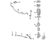
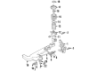
Steering Knuckle the part is arguably one of the components that speak of reliability and power of the full-size luxury sedan from Chrysler. As the connection between the suspension and steering departments of a car, the Steering Knuckle only assists to cause the front wheels to move while enhancing the manoeuvrability and stability of a vehicle. Designed to fit a number of Chrysler LHS models this Steering Knuckle works with rear-wheel (RWD) as well as with front/all-wheel (FWD/AWD/4WD) drive types, thus being very versatile. The steering knuckle of Chrysler LHS Sedan is extraordinary, and it offers good vertical as well as horizontal movements to the wheels, which automatics the movements of the wheel and also provides safety. This component calls for regular inspection and maintenance to maintain the performance of the vehicle as well as afford a smooth ride. As for the critical parts of the car's suspension, it is worth mentioning that the Steering Knuckle has rather heavy-duty bushings for the control arms and the tie-rod ends integrated into it, along with the heavily-loaded wheel hub. The use of engineering technology in Steering Knuckle enhances its performance in terms of handling as well as durability thereby making Steering Knuckle standout from other complexes of the same automotive market. In view of this, the Steering Knuckle performs a central contribution to the sustenance of the Chrysler LHS which owes its reputation on its luxury and high powered engines.
Chrysler LHS Steering Knuckle Parts and Q&A
- Q: How to Service a Steering Knuckle on Chrysler LHS?A:Before working on the steering knuckle, lift the vehicle up on jackstands or a frame contact hoist and take off the front wheel and tire assembly. Remove the front caliper from the steering knuckle and free the front rotor from the hub. Remove the wheel speed sensor to protect the outer C/V joint when you remove the hub and if the sensor can't move, use a hammer and punch to unseize it, not pliers. After that, take off the hub and bearing retaining nut, along with the three bolts connecting the steering knuckle to the hub and bearing assembly. Should the seal between the hub and bearing assembly jam and it is dislodged while removing it, then it has to be changed, as must any damaged flinger disc. Remove the hub and bearing from their place inside the steering knuckle by gently sliding them out. If it is stuck, carefully pry it out and gently knock the stub shaft with a soft face hammer. Carefully remove both stud nut and bolt so the ball joint seal remains clear of the steering knuckle. With a pry bar, split the ball joint from the steering knuckle and ensure you do not turn the bolts in the steering knuckle as you remove them. Lastly, take out the steering knuckle from the vehicle. Installation should start by connecting the steering knuckle to the ball joint stud and attaching it with the bolt, tightened to a torque of 55 Nm (40 ft. lbs.). Line up the steering knuckle with the strut assembly, avoiding twisting the bolts as you put them in, then tighten the strut clevis to steering knuckle attaching bolt nuts up to 203 Nm (150 ft. lbs.). See that the mounting surfaces are clean and not damaged, then set the hub and bearing assembly onto the stub shaft until it stays in position. Secure the hub and the bearing assembly to the three bolts and use a new retaining nut to fasten them all to 110 Nm (80 ft. lbs.). Cover the speed sensor head with High Temperature Multipurpose E.P. Grease before fitting, install it by hand with a seven Newtons millimetre (six inch pound) torque, replace the front brake rotor and caliper and tighten the caliper bolts to twenty Newtons millimetre (one hundred ninety inch pounds) torque. Following the application of the brakes, tighten the axle retaining nut to 142 Nm (105 ft. lbs.), put the wheel and tire assembly back on and tighten the wheel mounting stud nuts to 135 Nm (100 ft. lbs.) in the correct sequence. When lifted, remove the lift from the vehicle.

Related Chrysler LHS Parts
 Chrysler LHS Axle Support Bushings
 Chrysler LHS Bump Stop
 Chrysler LHS Coil Springs
 Chrysler LHS Lateral Link
 Chrysler LHS Shock Absorber
 Chrysler LHS Shock and Strut Boot
 Chrysler LHS Strut Housing
 Chrysler LHS Strut Mounts
 Chrysler LHS Suspension Strut Rod
 Chrysler LHS Sway Bars
 Chrysler LHS Trailing Arm
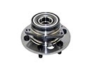 Chrysler LHS Wheel Hub