JeepParts
My Garage
My Account
Cart
OEM Chrysler Voyager Steering Knuckle
Front Steering Knuckle- Select Vehicle by Model
- Select Vehicle by VIN
Select Vehicle by Model
orMake
Model
Year
Select Vehicle by VIN
For the most accurate results, select vehicle by your VIN (Vehicle Identification Number).
14 Steering Knuckles found


Chrysler Voyager Knuckle, Front Driver Side Part Number: 4694953AB
$502.96 MSRP: $614.00You Save: $111.04 (19%)Ships in 1-2 Business Days
Chrysler Voyager Knuckle, Front Part Number: 4694822
$360.81 MSRP: $457.39You Save: $96.58 (22%)Ships in 1-2 Business Days
Chrysler Voyager Knuckle, Passenger Side Part Number: 68189018AE
$159.12 MSRP: $351.00You Save: $191.88 (55%)Ships in 1-2 Business DaysChrysler Voyager Knuckle - Suspension Part Number: 68621603AA
$224.32 MSRP: $342.00You Save: $117.68 (35%)Chrysler Voyager Knuckle - Suspension Part Number: 68621602AA
$224.32 MSRP: $342.00You Save: $117.68 (35%)Ships in 1 Business DayChrysler Voyager Knuckle, Front Driver Side Part Number: 68189019AE
$242.00 MSRP: $367.00You Save: $125.00 (35%)Ships in 1-2 Business DaysChrysler Voyager Knuckle, Front Driver Side Part Number: 68325423AA
$244.21 MSRP: $372.00You Save: $127.79 (35%)Chrysler Voyager Knuckle, Front Passenger Side Part Number: 68325422AA
$244.21 MSRP: $372.00You Save: $127.79 (35%)Ships in 1-2 Business Days
Chrysler Voyager Knuckle, Rear Passenger Side Part Number: 68325384AC
$289.51 MSRP: $442.00You Save: $152.49 (35%)Ships in 1-2 Business DaysChrysler Voyager Knuckle, Rear Driver Side Part Number: 68325385AC
$307.19 MSRP: $468.00You Save: $160.81 (35%)Ships in 1-2 Business Days


Chrysler Voyager Knuckle, Front Passenger Side Part Number: 4694952AB
Chrysler Voyager Knuckle, Front Part Number: 4694823
Chrysler Voyager Knuckle, Front Part Number: 5015934AA
Chrysler Voyager Knuckle, Front Part Number: 5015935AA
Chrysler Voyager Steering Knuckle
Choose OEM Steering Knuckle that meet Chrysler factory standards. Chrysler designs and tests every component for precision and durability. Each Steering Knuckle follows strict manufacturing steps to lock in quality and fit. If your Chrysler Voyager matters to you, OEM parts make the smart choice. You'll get the exact look, feel, and performance you expect. Shop genuine Voyager parts at the highly competitive prices online. Enjoy a manufacturer's warranty, a hassle-free return policy, and rapid delivery. No more guesswork with off brands. Get genuine parts with exact fit and true factory performance. Shop with confidence today at JeepPartsDeal.com.
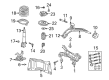
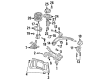
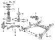
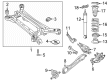
The Chrysler Voyager Steering Knuckle is a Automobile component that stands for both Durability and Performance as far as Chrysler Voyager is Concerned. Steering knuckle is an important component which connects the suspension system with the steering system of a car, allowing it to control the movement of the front wheels for the purpose of providing the car with the required stability. It is thus in four styles that correspond to the distinct drive-types of the automobile, RWD, FWD, AWD/4WD and improves flexibility on all types of Voyagers. Chrysler Voyager Steering Knuckle is designed to incorporate mounting devices for control arms, tie-rod ends, spindle as well as the hub in that enables vertical as well as horizontal wheel movement in relation to the driving surface. This functionality does not only help to increase the productivity of the vehicle but also plays a major role in increasing the safety of the vehicle by means of correct steering. Succeeding changes from simple kingpin systems to the present complex ball joint indicate a step forward in performance and stability hence Chrysler's stand. Actions: The Chrysler Voyager Steering Knuckle requires frequent inspections since it is a primary link within the vehicle's suspension, especially when the suspension components are substituted. The Chrysler Voyager Steering Knuckle occupies the high niche of the automotive market and effectively copes with the received tasks due to its durable design and compatibility with different models of Voyager, so the brand's reliability is reaffirmed again. All in all, the Chrysler Voyager Steering Knuckle is undoubtedly an important component that contributes to the vehicle's performance and safety; thus, it bears no doubt that the Chrysler Voyager is designed and manufactured to excel.
Chrysler Voyager Steering Knuckle Parts and Q&A
- Q: How to Service and Repair a Steering Knuckle on Chrysler Voyager?A:First, raise your vehicle using either a hoist or jack stands and then take off the wheel and tire. Then, remove both the cotter pin, nut lock and spring washer from the stub axle and hub nut. Either let a helper brake the wheel to stop the hub or put the hand brake on so the hub is held still while you remove the hub nut. Make sure to remove the disc Brake Caliper and adapter assembly from the knuckle and suspend it so it doesn't stress the brake hose. Take off the nut on the Tie Rod End stud with a wrench, remove the tie rod end and use the Remover, Special Tool C-389 to extract the end. Should the vehicle be fitted with antilock brakes, you need to remove the front wheel Speed Sensor from the steering knuckle. Loosen the two bolts that hold the steering knuckle to the strut clevis bracket, push the knuckle outwards and pull out the top of the driveshaft stub axle from the hub and bearing, allowing the driveshaft to hang straight down. Hold the ball joint stud with a hex wrench, remove the ball joint nut, then flex Remover, Special Tool C-4150A, around the ball joint stud to release it from the steering knuckle. After that, take the steering knuckle out of the vehicle. If you have to change the hub and bearing, first remove the four bolts that fix them to the knuckle. If installing the hub and bearing, set them in the steering knuckle so they are exactly lined up, add all four bolts and tighten them to 65 Nm (45 ft. lbs.). Before installing the knuckle on the ball joint stud, clean the area where they come together. Put the knuckle on the stud of the old ball joint, then screw in the new knuckle nut from the steering side. Apply a tightening torque of 108 Nm (80 ft. lbs.) by rotating a crowsfoot wrench on a torque wrench. Slide the stub axle onto the drive shaft and insert it into the hub and bearing. Hold the steering knuckle to strut assembly assembly together or use a suitable tool to prevent bolts from loosening as you install the shaft. Afterwards, bolt the steering knuckle to the strut clevis on the damper until it is tight, with 81 Nm (60 ft. lbs.) applied plus a 90° extra turn. Put the tie rod end on the knuckle steering arm, begin turning on the nut and tighten it to a final torque of 75 Nm (55 ft. lbs.), using a crowfoot and a torque wrench. Should your car have antilock brakes, set the wheel speed sensor in place and use a torque wrench to tighten the bolt to 7 Nm (60 inch lbs.). Bolt the brake rotor in place at the hub and bearing, add the disc brake caliper and connector and secure the two with adapter bolts that are tightened to 169 Nm (126 ft. lbs.). Gently pry out any attached debris on the outer C/V joint stub axle threads, put the washer and hub nut on, then tighten the hub nut to 244 Nm (180 ft. lbs.) while a helper stops the vehicle using the brakes. Insert the spring wave washer, put in the hub nut lock, replace the cotter pin and wrap its prongs around the hub nut lock tightly. Place the wheel and tire on the vehicle and torque only half the amount the book says to the nuts, then restart the process to the full value of 135 Nm (100 ft. lbs.). After that, drive the car back up and properly set the front wheel alignment camber and toe.
- Q: How to Remove and Install a Steering Knuckle on Chrysler Voyager?A:Before you can remove the steering knuckle, raise the vehicle and remove the wheel and its tire. After that, remove the cotter pin, nut lock and spring washer from the stub axle and hub nut. Have another person place their foot on the brakes before you loosen and take off the hub nut. Disconnect the whole disc brake system from the knuckle while suspending it away and avoiding stress to the brake hose. Pull the stud end while loosening the nut on the outer tie rod with a wrench. After that, remove the Tie Rod End using the Remover, Special Tool C-3894-A. If your vehicle is equipped with antilock brakes, take the front wheel Speed Sensor off the steering knuckle. After that, unscrew the bolts on the steering knuckle that attach it to the strut clevis bracket. Lift the knuckle to one side, remove the free end of the driveshaft axle from the hub and bearing and hang the driveshaft straight outward using a bungee cord or wire. Use a power impact wrench to take out the ball joint nut and after that, put it back on so it is even with the top of the ball joint stud to fix the damage. First, unfasten the ball joint stud from its mounting position with Remover, Special Tool C-4150A, then remove the nut on top of the ball joint. When that's done, you can remove the steering knuckle. If the hub and bearing should be taken out, take off the four holding bolts that are fastened to the knuckle. Examine the knuckle for any cracks, dents or marks and if you find them, the knuckle needs replacement. If placing the hub and bearing inside the knuckle, center them in the threaded holes and attach with four bolts secured to a torque of 65 Nm (45 ft. lbs.). Carefully wash the area of the ball joint stud that will touch the knuckle. Place the knuckle on the ball joint stud and fit a new nut over it, tighten the nut to 108 Nm (80 ft. lbs.) as you hold the stud firmly. Slide the driveshaft stub axle in place in the hub and bearing assembly so that it does not tighten or move the steering knuckle to strut assembly bolts. Place the steering knuckle into the strut damper and screw the clevis-to-steering knuckle bolts in until they reach 81 Nm (60 ft. lbs.) plus 90° of additional tightening. Fit the tie rod end into the knuckle steering arm, slide the nut onto the stud and tighten to 75 Nm or 55 ft. lbs. Should the car have antilock brakes, attach the wheel speed sensor and tighten the bolt to 7 Nm (60 in. lbs.). Place the brake rotor onto the hub and bearing, then bolt the disc Brake Caliper and adapter assembly in place using bolts tightened to 169 Nm (125 ft. lbs.). Wipe off any dirt on the outer C/V joint of the stub axle, put the washer in place and tighten the hub nut to 244 Nm (180 ft. lbs.) while someone presses the brakes. Add the spring wave washer, insert the hub nut lock and put on a fresh cotter pin, securing the prongs around the hub nut lock. Reattach the wheel and tire assembly and tighten the wheel mounts to 135 Nm (100 ft. lbs.) in sequence, after that, lower the vehicle and check the front wheel alignment camber and toe.


Related Chrysler Voyager Parts
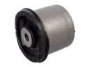 Chrysler Voyager Axle Beam Mount
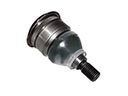 Chrysler Voyager Ball Joint
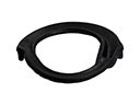 Chrysler Voyager Coil Spring Insulator
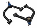 Chrysler Voyager Control Arm
 Chrysler Voyager Lateral Link
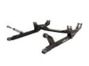 Chrysler Voyager Radius Arm
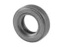 Chrysler Voyager Strut Bearing
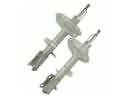 Chrysler Voyager Strut Housing
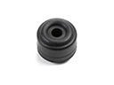 Chrysler Voyager Sway Bar Link Bushing
 Chrysler Voyager Sway Bars
 Chrysler Voyager Track Bar
 Chrysler Voyager Trailing Arm