JeepParts
My Garage
My Account
Cart
OEM Dodge Nitro Rod Bearing
Engine Connecting Rod Bearing- Select Vehicle by Model
- Select Vehicle by VIN
Select Vehicle by Model
orMake
Model
Year
Select Vehicle by VIN
For the most accurate results, select vehicle by your VIN (Vehicle Identification Number).
2 Rod Bearings found


Dodge Nitro Bearings Part Number: 68052222AB
$18.13 MSRP: $26.80You Save: $8.67 (33%)Ships in 1-2 Business Days


Dodge Nitro Connecting Rod Bearing Part Number: 68002286AC
$18.22 MSRP: $27.05You Save: $8.83 (33%)Ships in 1-3 Business Days
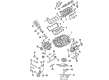
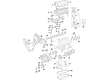
Dodge Nitro Rod Bearing
Choose OEM Rod Bearing that meet Dodge factory standards. Dodge designs and tests every component for precision and durability. Each Rod Bearing follows strict manufacturing steps to lock in quality and fit. If your Dodge Nitro matters to you, OEM parts make the smart choice. You'll get the exact look, feel, and performance you expect. Shop genuine Nitro parts at the highly competitive prices online. Enjoy a manufacturer's warranty, a hassle-free return policy, and rapid delivery. No more guesswork with off brands. Get genuine parts with exact fit and true factory performance. Shop with confidence today at JeepPartsDeal.com.
The Dodge Nitro Rod Bearing is a crucial part that effectively improves the durability as well as the capacity of Dodge Nitro automobiles. Purposefully manufactured to bear the important engine parts such as the crankshaft, the Rod Bearing keeps a layer of oil under pressure to ensure that there be a slippery surface for the said parts on which they can rotate seamlessly as required for the proper functioning of the automobile's engine. In bi-metal and tri-metal constructions, the Dodge Nitro Rod Bearing is highly put and is fitted to sit into the bearing saddles of the engine securely and durably. This is even more applicable to the Dodge Nitro manufactured from 2007 to 2012; this model is strong and delivers powerful performances. Tri-metal Rod Bearings, at times accompanied by special coatings, are designed to suit high power output engines and are much lighter in weight yet stronger, which is imperative for the continuation of Dodge Nitro's powerful performance. The Nitro's mechanical compatibility with different Rod Bearing models allows the owners to confidently improve both performance and security and thus stands out as a prominent feature in the car market. The Dodge Nitro Rod Bearing yet forms a mechanical part of the car contributing to the car's overall sturdiness and also helps in making certain the wear and tear of an engine does not occur at a fast pace thus safeguarding the car's engine. Being a reliable automotive company, the Dodge Nitro Rod Bearing is the ideal upgrade for any Nitro vehicle owner seeking to maximize the its capabilities.
Dodge Nitro Rod Bearing Parts and Q&A
- Q: How to Inspect and Replace Rod Bearings to Ensure Proper Alignment and Clearance on Dodge Nitro?A:Check the rod bearings for signs of scoring, usual patterns of wear, grooving, fatigue and holes and then replace any that are damaged. Look for scoring and nicks on connecting rod journals, because a bent or misaligned rod can result in unexpected wear on Pistons, piston rings, cylinder walls, connecting rod bearings and crankshaft journals. If wear spots or damage point to a misalignment, double-check the rod's placement and get rid of any rods that look misaligned, bent or twisted. Clean the oil from the connecting rod journal, apply lubricant to upper bearing insert and then put it in place centered in the connecting rod. Manually assemble the rod and piston into the cylinder using the piston ring compressor 3 and connecting rod guides 8507. Be sure the slots of the oil slinger in the rods face the engine front and the "F" marks near the piston wrist pin 1 are pointed there too. Center the new lower bearing insert in the connecting rod as you install it in the cap, being careful not to wet the insert. Touch the lower insert all along its width at the middle of the bearing cap, adding Plastigage so it doesn't crumble and verify the condition; repeat this if the original stock turns out to be brittle. Fit the bearing cap and connecting rod to the journal, fasten the bolts to 27 Nm (20 ft. lbs.) plus 90 degrees, but do not rotate the crankshaft to prevent the Plastigage from smearing and affecting results. Open the bearing cap, measure the pressed Plastigage and use Engine Specifications to check that the chosen bearing-to-journal clearance is correct. If the Plastigage reading varies along the insert, it could mean that the journal is tapered, the connecting rod is bent or something is trapped between the insert and the cap or rod. If the bearing inserts pass clearance, do not replace them; remove the Plastigage and get ready to install the bearing. If the gap between the bearing and the journal is greater than allowed, choose a different bearing set and always replace the rod bolts whenever you deal with them. Make sure to repeat using Plastigage to verify the suitability of the bearing before assembling the machine. When the right insert is found, install the insert and cap, turning the bolts that connect them to 27 Nm (20 ft. lbs.) plus a full 90 degree turn. Put a feeler gauge with a tight fit between the connecting rod and crankshaft journal, check the clearance specified by the manufacturer and swap the connecting rod if the minimum is exceeded.

Related Dodge Nitro Parts
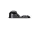 Dodge Nitro Oil Pan
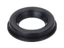 Dodge Nitro Camshaft Seal
 Dodge Nitro Crankshaft Gear
 Dodge Nitro Crankshaft Seal
 Dodge Nitro Cylinder Head Gasket
 Dodge Nitro Engine Mount Bracket
 Dodge Nitro Exhaust Valve
 Dodge Nitro Harmonic Balancer
 Dodge Nitro Oil Pump Gasket
 Dodge Nitro Piston
 Dodge Nitro Rocker Arm
 Dodge Nitro Timing Cover