JeepParts
My Garage
My Account
Cart
OEM Dodge Ram 1500 Van Exhaust Valve
Exhaust Muffler Valve- Select Vehicle by Model
- Select Vehicle by VIN
Select Vehicle by Model
orMake
Model
Year
Select Vehicle by VIN
For the most accurate results, select vehicle by your VIN (Vehicle Identification Number).
1 Exhaust Valve found

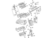
Dodge Ram 1500 Van Exhaust Valve Part Number: 53006724
Dodge Ram 1500 Van Exhaust Valve
Choose OEM Exhaust Valve that meet Dodge factory standards. Dodge designs and tests every component for precision and durability. Each Exhaust Valve follows strict manufacturing steps to lock in quality and fit. If your Dodge Ram 1500 Van matters to you, OEM parts make the smart choice. You'll get the exact look, feel, and performance you expect. Shop genuine Ram 1500 Van parts at the highly competitive prices online. Enjoy a manufacturer's warranty, a hassle-free return policy, and rapid delivery. No more guesswork with off brands. Get genuine parts with exact fit and true factory performance. Shop with confidence today at JeepPartsDeal.com.
Dodge Ram 1500 Van Exhaust Valve Parts and Q&A
- Q: How should Exhaust Valve and Intake Valve be cleaned, inspected, and serviced on Dodge Ram 1500 Van?A:Make sure the valves are free of debris before getting rid of any that seem burned, warped or cracked. Using a guide cleaner, take out any visible carbon and varnish residue inside the valve guides. Check how much the valve stems have worn out and change them if they pass 0.051 mm (0.002 inch). Measure valve stem guide clearance by sliding Valve Guide Sleeve Tool C-3973 over the valve stem, fitting the valve and confirming that the special sleeve positions it correctly for reading with a dial indicator. Put dial indicator Tool C-3339 onto the cylinder head at a right angle to the measured valve stem, move the valve back and forth and note that the total reading does not go above 0.432 mm (0.017 inch). Use a valve thirumover for valves with overloaded stems. Service valves with oversized stems can be obtained and before putting in a new valve, hand-turn the cleaner reamer down the guide to make sure the inside is clean, reaming the guide from nominal to 0.016 inch in two parts, starting with 0.003 inch and finishing with 0.016 inch. Both the intake and exhaust valves measure 43-1/4° to 43-3/4° in face angle and 44-1/4° to 44-3/4° in seat angle. After the refacing process, examine the remainder of the ball's margin; if it is less than 1.190 mm (0.047 inch), you should remove it from use. To ensure a correct surface when using valve seat stones, insert the right size valve guide pilot to assist the reseating process. Run a dial indicator on the valve seat to confirm that total runout is less than 0.051 mm (0.002 inch). Apply Prussian blue to the valve seat; the blue indicates contact if it appears at the center of the valve face. Should it run out from the top of the valve seat, lower it with a 15° stone; if from the bottom edge, raise with a 60° stone. The width of intake seats needs to be 1.016 - 1.524 mm (0.040 - 0.060 inch) and the width of exhaust seats should be 1.524 - 2.032 mm (0.060 - 0.080 inch). anytime you remove a valve for inspection, reconditioning or replacement, check the valve springs. Suppose the test spring's compression length is 1-5/16 in. Make sure the end of the valve spring tester-its zero mark-is at the front, as you guide it to the 1-5/16 in. mark on the valve spring tester threaded stud. Place the spring on the stud and pull the lever to adjust the look of the tone device. Pull the torque wrench until you hear a ping, look at its reading and multiply it by 2 to find the load at test length. If you need very fine changes, refer to the table's fractional measurements and throw out any spring that doesn't follow the listing.

Related Dodge Ram 1500 Van Parts
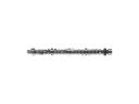 Dodge Ram 1500 Van Camshaft
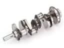 Dodge Ram 1500 Van Crankshaft
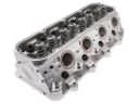 Dodge Ram 1500 Van Cylinder Head
 Dodge Ram 1500 Van Dipstick Tube
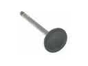 Dodge Ram 1500 Van Intake Valve
 Dodge Ram 1500 Van Lash Adjuster
 Dodge Ram 1500 Van Oil Filter
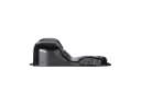 Dodge Ram 1500 Van Oil Pan
 Dodge Ram 1500 Van Pushrod
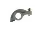 Dodge Ram 1500 Van Rocker Arm
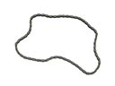 Dodge Ram 1500 Van Timing Chain
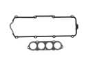 Dodge Ram 1500 Van Valve Cover Gasket