JeepParts
My Garage
My Account
Cart
OEM Dodge Stratus Ball Joint
Control Arm Joint- Select Vehicle by Model
- Select Vehicle by VIN
Select Vehicle by Model
orMake
Model
Year
Select Vehicle by VIN
For the most accurate results, select vehicle by your VIN (Vehicle Identification Number).
2 Ball Joints found


Dodge Stratus Stabilizer Link, Front Part Number: 4695626
$74.74 MSRP: $81.90You Save: $7.16 (9%)Ships in 1-2 Business Days
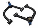
Dodge Stratus Ball Joint, Rear Upper Part Number: 4879321AC
$84.12 MSRP: $212.00You Save: $127.88 (61%)Ships in 1-2 Business Days
Dodge Stratus Ball Joint
Choose OEM Ball Joint that meet Dodge factory standards. Dodge designs and tests every component for precision and durability. Each Ball Joint follows strict manufacturing steps to lock in quality and fit. If your Dodge Stratus matters to you, OEM parts make the smart choice. You'll get the exact look, feel, and performance you expect. Shop genuine Stratus parts at the highly competitive prices online. Enjoy a manufacturer's warranty, a hassle-free return policy, and rapid delivery. No more guesswork with off brands. Get genuine parts with exact fit and true factory performance. Shop with confidence today at JeepPartsDeal.com.
The Dodge Stratus Ball Joint regarded as the critical component in the suspension and steering of Dodge Stratus models, which are famous in their reliability and power. It joins the control arms to the steering knuckles and lets the latter rotate and turn in the right direction without wobbling, improving vehicle control and Stability. Applicable for the following models of Dodge Stratus made from 1995 - 2005, the Ball Joint can take a beating and would be suitable for everyday use. Made of steel and sealed the Dodge Stratus Ball Joint does not require frequent lubrication and has an expected lifetime of about 80000 miles. This longevity is accompanied by high-performance versions that make use of spherical rolling joints that has low friction and high stiffness enhancing the efficiency and safety. Dodge Stratus is both a sedan and coupe type of car having a distinctive design, and high engine power, thus, the importance of the Ball Joint in achieving the optimal rendition of the car's mechanics. In the automotive market the Dodge Stratus Ball Joint is a distinct addition since it combines safety and efficiency that is a win-win for the driver. In general, the Dodge Stratus Ball Joint reflects the company's adherence to strength and speed, providing comfortable and safe travel.
Dodge Stratus Ball Joint Parts and Q&A
- Q: How to Service and Repair a Ball Joint on Dodge Stratus?A:Begin by gently pulling the Ball Joint Seal Boot (Upper) off the ball joint hammer assembly with a screwdriver or a similar tool. Then, place a New ball joint assembly sealing boot around the top of the ball joint assembly, pushing it as far as it will come. Having too much force applied during installation can harm the sealing boot which is why an arbor press should be avoided. Cover the sealing boot with Special Tool 6758 and push it toward the edge using your hand until the boot is held close to and squarely fitted on the upper Control Arm. Put some Mopar Multi-Mileage Lube or a compatible substitute into the upper ball joint assembly at the end.
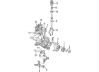
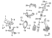
- Q: How to Replace a Ball Joint on Dodge Stratus?A:Before you replace the upper ball joint, take out the rear upper Control Arm. To hold the control arm, place Position Receiving Cup, Special Tool 6758, under it and insert Remover/Installer, Special Tool 6804, onto the ball joint assembly. Pull the ball joint assembly out of the control arm by using an arbor press. If you discover physical damage to the control arm, it should be replaced, because it is impossible to fix. If the pivot bushings on the control arm can be seen to be worn, then you must change the entire control arm. The assembly of the rear control arm, bushings and pivot connector are replaced all at once, but the rear upper ball joint and its seal can be serviced individually. Hold the ball joint assembly up to the ball joint bore on the control arm, pointing it straight up and down, without cocking it during installation. Attach the Receiving Cup Tool 6758 to the arbor press and grip the lower control arm. Add the Supports, Special Tool 6806, to the ball joint assembly above and insert the Remover/Installer tool 6804. Hold back the ball joint enough to leave a clear space of 3 mm (1/8 inch) between its lip and the control arm. After that, refit the control arm to the suspension, lining up the pivot bar with the holes in the rear suspension crossmember and fastening the 2 bar attaching bolts to 108 Nm (80 ft. lbs.). Lift the rear suspension crossmember with a transmission jack and put the four attaching bolts in place, but do not tighten them. Use the correct drift size to line up the rear suspension crossmember, fasten all crossmember to frame attaching bolts to 108 Nm (80 ft. lbs.) and take out the drifts. Take out the transmission jack, attach the upper ball joint stud to the knuckle and tighten the ball joint nut to 27 Nm (20 ft. lbs.). Place the brake tubing into the routing clips on the top of the rear suspension crossmember and fasten the rear Brake Calipers to the rear knuckles. Should the car be equipped with antilock brakes, place wheel speed sensor heads at the top of each rear knuckle and torque the sensor mounting bolts to 8 Nm. Fasten the routing clips to the brackets on each upper control arm for the wheel speed sensor cables and make sure the attaching bolts are secure. Fasten the muffler support bracket to the back of the frame rail and click the rear exhaust pipe hanger on the back of the suspension crossmember. Attach the rear knuckle clevis brackets, then tighten the bolts to 95 Nm (70 ft. lbs.). Mount the wheel and tire and, working from one side to another, tighten the wheel nuts by quarter increments until the final 135 Nm (100 ft. lbs.). Suspend the vehicle and correct or reset the rear wheel camber and toe, following the ideal specifications required.


Related Dodge Stratus Parts
 Dodge Stratus Control Arm
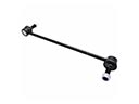 Dodge Stratus Sway Bar Link
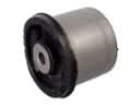 Dodge Stratus Axle Beam Mount
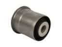 Dodge Stratus Axle Support Bushings
 Dodge Stratus Crossmember Bushing
 Dodge Stratus Lateral Link
 Dodge Stratus Leaf Spring Bushing
 Dodge Stratus Radius Arm
 Dodge Stratus Radius Arm Bushing
 Dodge Stratus Shock Absorber
 Dodge Stratus Sway Bar Bracket
 Dodge Stratus Sway Bars