JeepParts
My Garage
My Account
Cart
OEM Jeep Compass Steering Knuckle
Front Steering Knuckle- Select Vehicle by Model
- Select Vehicle by VIN
Select Vehicle by Model
orMake
Model
Year
Select Vehicle by VIN
For the most accurate results, select vehicle by your VIN (Vehicle Identification Number).
12 Steering Knuckles found


Jeep Compass Knuckle, Front Passenger Side Part Number: 68088498AD
$259.96 MSRP: $585.00You Save: $325.04 (56%)Ships in 1-2 Business Days


Jeep Compass Knuckle, Driver Side Part Number: 4787958AA
$225.68 MSRP: $498.00You Save: $272.32 (55%)


Jeep Compass Knuckle, Front Passenger Side Part Number: 68088536AD
$376.81 MSRP: $573.00You Save: $196.19 (35%)Ships in 1-2 Business Days


Jeep Compass Knuckle, Front Driver Side Part Number: 68088535AD
$376.81 MSRP: $573.00You Save: $196.19 (35%)Ships in 1-2 Business Days
Jeep Compass Knuckle, Driver Side Part Number: 68282577AE
$292.83 MSRP: $447.00You Save: $154.17 (35%)Ships in 1-2 Business Days
Jeep Compass Knuckle - Suspension Part Number: 68291104AF
$296.14 MSRP: $452.00You Save: $155.86 (35%)Jeep Compass Knuckle - Suspension Part Number: 68291105AF
$311.61 MSRP: $475.00You Save: $163.39 (35%)Jeep Compass Knuckle, Passenger Side Part Number: 4787970AA
$371.28 MSRP: $565.00You Save: $193.72 (35%)Ships in 1-2 Business DaysJeep Compass Knuckle, Front Driver Side Part Number: 68088499AD
$384.54 MSRP: $585.00You Save: $200.46 (35%)Ships in 1-2 Business Days

Jeep Compass Knuckle, Rear Driver Side Part Number: 68246625AA
$250.73 MSRP: $450.00You Save: $199.27 (45%)Ships in 1-2 Business DaysJeep Compass Knuckle, Rear Passenger Side Part Number: 68246619AA
$298.35 MSRP: $450.00You Save: $151.65 (34%)Ships in 1-2 Business DaysJeep Compass Knuckle, Passenger Side Part Number: 68282576AE
$319.52 MSRP: $452.00You Save: $132.48 (30%)
Jeep Compass Steering Knuckle
Choose OEM Steering Knuckle that meet Jeep factory standards. Jeep designs and tests every component for precision and durability. Each Steering Knuckle follows strict manufacturing steps to lock in quality and fit. If your Jeep Compass matters to you, OEM parts make the smart choice. You'll get the exact look, feel, and performance you expect. Shop genuine Compass parts at the highly competitive prices online. Enjoy a manufacturer's warranty, a hassle-free return policy, and rapid delivery. No more guesswork with off brands. Get genuine parts with exact fit and true factory performance. Shop with confidence today at JeepPartsDeal.com.
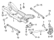
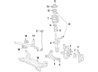
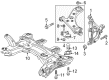
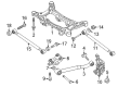
The Knuckle of Jeep Compass vehicles is an important structural unit that linking of suspension and steering systems to the front wheels. It offers the means of mounting of the control arms, tie-rod ends or spindle or hubs, for up and down movement based on road surface irregularities and sideways movement during steered input. Steering knuckles in Jeep Compass models depend on models' drive type front-wheel/all-wheel/four-wheel drive/ rear-wheel drive differentials. Among them the most significant are whether the knuckle is forged and the spindle welded to it, or whether the hub can be bolted to the spindle. Steering knuckles are typically strong parts but if they are worn out or in case other parts connected to the steering knuckles such as ball joint or tie-rod ends have been damaged, then they need replacement. Altogether, the Knuckle is useful for keep the wheel stability and control of Jeep Compass automobiles.
Jeep Compass Steering Knuckle Parts and Q&A
- Q: How to Remove a Front Steering Knuckle on Jeep Compass?A:Before you remove the front steering knuckle, make sure the car is raised and supported, slide out the wheel nuts and remove the entire wheel assembly. After that, remove the cotter pin, lock and spring washer from the stub shaft of the halfshaft. Your helper should apply the brakes to prevent the hub from spinning; afterward, take the hub nut and washer out. Get to your front brake rotor and take it off. After taking off the routing clip, remove the screw and pull the wheel speed sensor head straight out from where it is mounted to the knuckle. Rotate the knuckle with a torque wrench and use a wrench on the end of the tie rod to turn it as you loosen the bolt attaching the nut to the rod. Use Remover, Special Tool 9360, to disconnect the outer tie rod end from the knuckle and then take out the outer tie rod. Then, get rid of the pinch bolt that holds the ball joint stud in place, making sure the strut assembly-to-knuckle bolts aren't touched while you remove the nut to keep them in place. Anchor the bolt heads before taking the nuts off the bolts linking the strut to the knuckle and remove those bolts using a pin punch. Spread the ball joint stud away from the knuckle so you don't damage the ball joint seal. Then place your prying tool on the bottom of the Control Arm and push against the ball joint boss on the knuckle. Support the half shaft to stop the inner C/V joint from parting and pull the knuckle clear of the outer C/V joint corded splines to get it off the vehicle.
- Q: How is the Steering Knuckle Installed on the Front on Jeep Compass?A:Position the hub on the outer C/V joint vertically and from beneath the car, slide the knuckle completely onto the splines. Match the shape of the knuckle's bolt hole with the groove on the ball joint stud, then push the knuckle onto the stud. Fit the ball join stud with a new pinch bolt and nut, tighten it to 82 Nm (60 ft. lbs.). Before installing, ensure the strut assembly-to-knuckle bolts which are serrated, do not move; tighten the nuts without turning the serrated bolts. Line up the lower part of the strut assembly with the upper part of the knuckle, check that the mounting holes are aligned and put in the two bolts. Slip each nut onto a bolt and use a torque wrench to tighten each set to 84 Nm (62 ft. lbs.). Slide the tie rod ball stud from the outside into the knuckle arm, attach the tie rod end-to-knuckle nut to the stud and tighten this nut by 132 Nm (97 ft. lbs.) with a wrench. Set the wheel speed sensor head into the knuckle, tighten its screw to 12 Nm (106 in. lbs.) and connect the routing clip to the sensor position. Add the brake rotor, disc Brake Caliper and adapter to the system. Clean the halfshaft outer C/V joint afterward and place the washer, tightening the hub nut with a wrench. With the help of a pedaler preventing the hub from rotating, tighten the hub nut to 245 Newton meters (181 foot-pounds). Position the cotter pin through both the nut's notches and the hole in the halfshaft. After securing the nut so that the notches sit in alignment without wobbling, wrap the ends of the cotter pin firmly over the lock nut. Place the tire and wheel onto the car and align the wheel so the nuts touch the studs inside the fender well. Then, tighten the nuts to 135 Nm (100 ft. lbs.) and bring the vehicle down onto the ground. If the knuckle is being fitted as before, the Net-Build design may mean wheel alignment is not required, but do it if needed.


Related Jeep Compass Parts
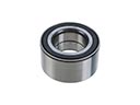 Jeep Compass Wheel Bearing
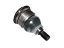 Jeep Compass Ball Joint
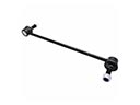 Jeep Compass Sway Bar Link
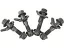 Jeep Compass Camber and Alignment Kit
 Jeep Compass Coil Spring Insulator
 Jeep Compass Coil Springs
 Jeep Compass Control Arm Bolt
 Jeep Compass Radius Arm
 Jeep Compass Shock and Strut Boot
 Jeep Compass Strut Mounts
 Jeep Compass Sway Bar Link Bushing
 Jeep Compass Track Bar