JeepParts
My Garage
My Account
Cart
OEM 2001 Dodge Grand Caravan ABS Control Module
Anti Lock Brake Control Module- Select Vehicle by Model
- Select Vehicle by VIN
Select Vehicle by Model
orMake
Model
Year
Select Vehicle by VIN
For the most accurate results, select vehicle by your VIN (Vehicle Identification Number).
4 ABS Control Modules found


2001 Dodge Grand Caravan Modulator Valve Part Number: 5018252AA
Product Specifications- Other Name: Accumulator - Anti-Lock Brake System; ABS Hydraulic Assembly; ABS Control Module; ABS Control Unit; Hydraulic Control Unit Anti-Lock Brake System
- Item Weight: 5.10 Pounds
- Item Dimensions: 7.3 x 7.0 x 6.7 inches
- Condition: New
- Fitment Type: Direct Replacement
- SKU: 5018252AA
- Warranty: This genuine part is guaranteed by Mopar's factory warranty.

2001 Dodge Grand Caravan Control Module Part Number: 5093988AA
Product Specifications- Other Name: Control - Anti-Lock Brakes; ABS Control Module; Electronic Control; Module Anti-Lock Brakes With Mounting Screws; Module Anti-Lock Brakes
- Replaces: 5086175AA
- Item Weight: 2.10 Pounds
- Item Dimensions: 5.8 x 4.4 x 2.7 inches
- Condition: New
- Fitment Type: Direct Replacement
- SKU: 5093988AA
- Warranty: This genuine part is guaranteed by Mopar's factory warranty.
2001 Dodge Grand Caravan Control Module Part Number: 5093986AA
Product Specifications- Other Name: Control - Anti-Lock Brakes; ABS Control Module; Electronic Control; Module Anti-Lock Brakes With Mounting Screws; Module Anti-Lock Brakes
- Replaces: 5086174AA
- Item Weight: 2.00 Pounds
- Item Dimensions: 5.8 x 4.7 x 2.8 inches
- Condition: New
- Fitment Type: Direct Replacement
- SKU: 5093986AA
- Warranty: This genuine part is guaranteed by Mopar's factory warranty.
2001 Dodge Grand Caravan Modulator Valve Part Number: 5018253AA
Product Specifications- Other Name: Accumulator - Anti-Lock Brake System; ABS Hydraulic Assembly; ABS Control Module; ABS Control Unit; Hydraulic Control Unit Anti-Lock Brake System
- Item Weight: 6.20 Pounds
- Item Dimensions: 7.3 x 7.2 x 6.4 inches
- Condition: New
- Fitment Type: Direct Replacement
- SKU: 5018253AA
- Warranty: This genuine part is guaranteed by Mopar's factory warranty.
2001 Dodge Grand Caravan ABS Control Module Parts and Q&A
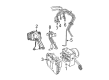
- Q: How to Remove and Install the ABS Control Module for Antilock Brakes on 2001 Dodge Grand Caravan?A: Before removing the Hydraulic Control Assembly, take out the negative battery cable, isolate it and next take out the battery shield and the battery. Unplug the vacuum hose at the tank inside the battery tray, take out the screw at the engine coolant filler neck secured to the battery tray and then remove the battery tray. Apply a brake pedal depressor to the brake pedal, stopping it in place past the first inch, so brake fluid from the master cylinder doesn't leak out when you take the brake lines from the Hydraulic Control Unit. Don't use a 12-volt power source on any terminals of the 24-way Controller Antilock Brake connector after it has been disconnected. First, pull the wiring harness out of the speed control servo, then remove the nuts and set the servo somewhere else. To disconnect, grasp the lock and pull it up on the 24-way connector from the CAB. Wipe down the Integrated Control Unit and brake tube nuts using Mopar Brake Parts Cleaner and then take the brake tubes out of the HCU's outlet and inlet ports. Lean the steering wheel up and to the left, take off the silencer panel below the instrument panel, remove the bolt at the steering shaft coupling and unclip and unscrew the silencer from the dash seal. Take off the bolts that link the ICU to the bracket and draw out the ICU through the engine compartment. To install, lower the ICU bracket under the master cylinder and begin the upper bolt. Afterwards, install the two remaining mounting bolts inside the vehicle and tighten them all to 11 Nm. Add the dash seal along with the three screws and then put the silencer over it. Place the steering shaft coupling back and tighten the pinch bolt to 28 Nm. Secure the silencer panel under your main dashboard, remove the mount for the steering wheel and take care that both your brake pipes are inline when you put everything together. Insert the brake tubes into the right ports on the HCU valve block, then use a torque wrench to tighten their nuts down to 17 Nm. Follow the brake tube route arrows on the HCU and install each tube into its correct port on the valve block. Make sure to tighten the tube nuts with 17 Nm of torque. It is important to install the seal in the 24-way connector first, before putting it into the CAB port and pressing it down firmly. Attach the routing clips to the brake tubes, push the pedal holder into the holder portion and secure the speed control servo with its nuts. Attach the wiring harness to the speed control servo, fix the battery tray into place and close its securing screw, reconnect the vacuum hose and then place the battery and its cover back on the battery shield. Afterward, reconnect the negative cable to the battery, bleed the Base and ABS brake hydraulic systems and check that both systems work by going on a test drive.
Related 2001 Dodge Grand Caravan Parts
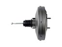 2001 Dodge Grand Caravan Brake Booster
 2001 Dodge Grand Caravan Brake Caliper
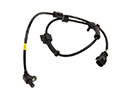 2001 Dodge Grand Caravan Speed Sensor
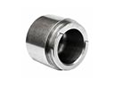 2001 Dodge Grand Caravan Brake Caliper Piston
 2001 Dodge Grand Caravan Brake Disc
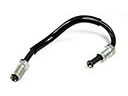 2001 Dodge Grand Caravan Brake Line
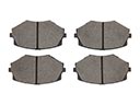 2001 Dodge Grand Caravan Brake Pad
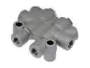 2001 Dodge Grand Caravan Brake Proportioning Valve
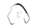 2001 Dodge Grand Caravan Hydraulic Hose
 2001 Dodge Grand Caravan Parking Brake Shoe
 2001 Dodge Grand Caravan Wheel Cylinder
 2001 Dodge Grand Caravan Wheel Stud