JeepParts
My Garage
My Account
Cart
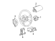
OEM 2003 Dodge Neon Clock Spring
Spiral Cable Clock Spring- Select Vehicle by Model
- Select Vehicle by VIN
Select Vehicle by Model
orMake
Model
Year
Select Vehicle by VIN
For the most accurate results, select vehicle by your VIN (Vehicle Identification Number).
4 Clock Springs found

2003 Dodge Neon Clockspring Part Number: 4671946AC
$329.46 MSRP: $380.00You Save: $50.54 (14%)Ships in 1-2 Business DaysProduct Specifications- Other Name: Air Bag Clockspring
- Replaces: 4671946AB
- Item Weight: 0.80 Pounds
- Item Dimensions: 5.0 x 4.1 x 4.1 inches
- Condition: New
- Fitment Type: Direct Replacement
- SKU: 4671946AC
- Warranty: This genuine part is guaranteed by Mopar's factory warranty.
2003 Dodge Neon Clockspring Part Number: 4671945AB
Product Specifications- Other Name: Air Bag Clockspring
- Replaces: 4671945AA
- Item Weight: 0.80 Pounds
- Item Dimensions: 4.5 x 4.2 x 2.0 inches
- Condition: New
- Fitment Type: Direct Replacement
- SKU: 4671945AB
- Warranty: This genuine part is guaranteed by Mopar's factory warranty.
2003 Dodge Neon Clockspring Part Number: 4671753AE
Product Specifications- Other Name: Air Bag Clockspring
- Replaces: 4671753AD
- Item Weight: 0.80 Pounds
- Item Dimensions: 4.7 x 4.2 x 3.8 inches
- Condition: New
- Fitment Type: Direct Replacement
- SKU: 4671753AE
- Warranty: This genuine part is guaranteed by Mopar's factory warranty.
2003 Dodge Neon Clockspring Part Number: 4671754AE
Product Specifications- Other Name: Air Bag Clockspring
- Condition: New
- Fitment Type: Direct Replacement
- SKU: 4671754AE
- Warranty: This genuine part is guaranteed by Mopar's factory warranty.
2003 Dodge Neon Clock Spring Parts and Q&A
- Q: How to Service and Repair a Clock Spring Assembly on 2003 Dodge Neon?A: Start by placing the front road wheels at the driving position and rotate the steering wheel to the right so it goes from lock to lock (half turn). Then lock the steering wheel in place with the ignition lock. Unplug the negative cable of the battery, let the reserve capacitor drain for a minute and after that remove the non-deployed module. Once you've removed the steering wheel, also remove the upper steering column shroud and the lower steering column shroud to work on the Clock Spring wiring. After that, remove the multi-function switch and unplug the connector between the Clock Spring and instrument panel wiring harness at its bottom. Raise the top tab on the latch slightly and remove the Clock Spring; if defective, it has to be replaced. Turn the Clock Spring rotor one-quarter turn to the right, put a paper clip wire in the center and bend it to keep the rotor in place. During installation, the steering wheel needs to be turned half turn (180 degrees) to the right, the column must be locked and the turn signal stalk should be neutral. If you plan to reuse your Clock Spring, take off the locking wire and turn the rotor one half rotation (to the right) before finding the Clock Spring on the steering shaft and seating it by pushing down. To install a brand new Clock Spring, point the front wheels forward, remove the grenade pin and rotate the rotor one half turn to the necklace (180 degrees) in a clockwise direction. Hook up the Clock Spring to the instrument panel wiring, guaranteeing all parts are lined up properly and that all connectors are secured. Attach the multi-function switch and afterward add the steering column shrouds, ensuring all wires enter the columns from the bottom. Connect the steering wheel so that the flat sides on the hub fit onto the Clock Spring and make sure all the leads for the horn, air bag and speed control are pushed through the large slot in the firewall to prevent pinch damage. Place your speed control wires below and behind the tabs for the air bag module, connect the end of the horn lead wire and air bag lead wire to the air bag module and install the air bag module, securing bolts with 12 to 14 Nm (105 to 125 in. lbs.) of torque. Following that, link the speed control wires to the switches, install them and ensure the screws are tightened to 2 Nm (20 in. lbs.). Never connect the battery negative cable until you have checked and tested the air bag system first.
Related 2003 Dodge Neon Parts
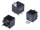 2003 Dodge Neon Fuel Pump Relay
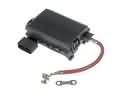 2003 Dodge Neon Fuse Box
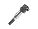 2003 Dodge Neon Ignition Coil
 2003 Dodge Neon Ignition Lock Cylinder
 2003 Dodge Neon Power Window Switch
 2003 Dodge Neon Air Bag
 2003 Dodge Neon Air Bag Control Module
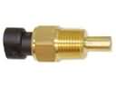 2003 Dodge Neon Coolant Temperature Sensor
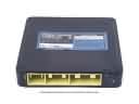 2003 Dodge Neon Engine Control Module
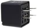 2003 Dodge Neon Relay
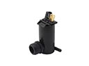 2003 Dodge Neon Washer Pump
 2003 Dodge Neon Window Motor