JeepParts
My Garage
My Account
Cart
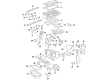
OEM 2005 Chrysler PT Cruiser Piston
Engine Pistons- Select Vehicle by Model
- Select Vehicle by VIN
Select Vehicle by Model
orMake
Model
Year
Select Vehicle by VIN
For the most accurate results, select vehicle by your VIN (Vehicle Identification Number).
2 Pistons found


2005 Chrysler PT Cruiser Vibration Damper Part Number: 5142303AB
$56.55 MSRP: $81.25You Save: $24.70 (31%)Ships in 1-3 Business DaysProduct Specifications- Other Name: Piston; Piston Pin And Rod
- Replaces: 5142303AA, 5066565AB
- Item Weight: 3.00 Pounds
- Item Dimensions: 5.7 x 4.4 x 12.6 inches
- Condition: New
- Fitment Type: Direct Replacement
- SKU: 5142303AB
- Warranty: This genuine part is guaranteed by Mopar's factory warranty.

2005 Chrysler PT Cruiser Piston Part Number: 4884247AD
Product Specifications- Other Name: Piston Pin And Rod; Piston Pin And Rod
- Replaces: 4884247AC
- Item Weight: 3.10 Pounds
- Item Dimensions: 13.7 x 6.2 x 4.6 inches
- Condition: New
- Fitment Type: Direct Replacement
- SKU: 4884247AD
- Warranty: This genuine part is guaranteed by Mopar's factory warranty.
2005 Chrysler PT Cruiser Piston Parts and Q&A
- Q: How to Replace a Piston and Its Connecting Rod on 2005 Chrysler PT Cruiser?A: Let's remove the cylinder head, the oil pan and the Balance Shaft Carrier Assembly first to unfasten the piston and its connecting rod. Take off the top of the cylinder bores with a trustworthy ridge reamer while covering the top of the pistons. You'll see that there is a stamp showing the direction of the piston on the side facing the front of the engine. Run the crankshaft until the connecting rods are aligned in the center of the cylinders, then remove the pistons and rods from above the cylinder block. Tag the middle of the connecting rod cap with the matching cylinder number marking them with a permanent ink or paint marker and not a number stamp or punch. Remove the bolts and cap that hold the connecting rod together, making sure not to damage either end of the fracture rod or cap and do not recycle the bolts. Place Special Tool 8189 around the crankshaft journal and each broken rod shaft to cover and care for them as you carefully force pistons and rods through the cylinder bore so as not to damage the oil jet assembly on Turbocharger engines. Once you remove the guides, replace the bearing cap onto the mating rod. Do the same process for every group of piston and connecting rod, then uninstall the piston rings. Before snugging the piston with the ring compressor, put the piston rings in place, with their gaps staggered and their expander ends touching, to start the installation. Dip the piston head and rings in clean engine oil, put the ring compressor over the piston and watch that the ring positions do not shift. It's important for the piston's directional stamp to be at the front of the engine. Wind the crankshaft to bring the connecting rod journal into the center of the bore and coat this part with clean engine oil. First, set the upper bearing half onto the connecting rod, then insert Special Tool 8189, put on the connecting rod guides and if you guide the connecting rod and tap down the piston as you go, it will settle into place. Take out the guides so the bolts from the connecting rod cap are not used again. Hot move the bolt threads over clean engine oil, put the lower bearing into the connector rod cap and install the cap. Temper the nuts by hand and without assistance until each bolt is tight enough to move, then torque each bolt exactly to 27 Nm (20 ft. lbs.) in alternating order and for the second step, tighten each bolt another 1/4 turn by hand without a torque wrench. First, check the space on the connecting rod side with a gauge, then set the Balance Shaft Carrier Assembly, oil pan and cylinder head in place.
Related 2005 Chrysler PT Cruiser Parts
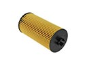 2005 Chrysler PT Cruiser Oil Filter
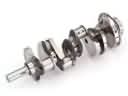 2005 Chrysler PT Cruiser Crankshaft
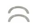 2005 Chrysler PT Cruiser Crankshaft Thrust Washer Set
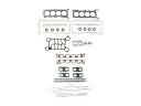 2005 Chrysler PT Cruiser Cylinder Head Gasket
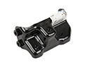 2005 Chrysler PT Cruiser Engine Mount Bracket
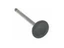 2005 Chrysler PT Cruiser Intake Valve
 2005 Chrysler PT Cruiser Oil Filler Cap
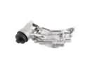 2005 Chrysler PT Cruiser Oil Filter Housing
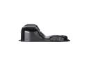 2005 Chrysler PT Cruiser Oil Pan
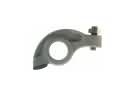 2005 Chrysler PT Cruiser Rocker Arm
 2005 Chrysler PT Cruiser Timing Chain Tensioner
 2005 Chrysler PT Cruiser Valve Stem Seal