JeepParts
My Garage
My Account
Cart
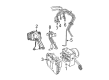
OEM 2006 Dodge Caravan ABS Control Module
Anti Lock Brake Control Module- Select Vehicle by Model
- Select Vehicle by VIN
Select Vehicle by Model
orMake
Model
Year
Select Vehicle by VIN
For the most accurate results, select vehicle by your VIN (Vehicle Identification Number).
4 ABS Control Modules found


2006 Dodge Caravan Modulator Valve Part Number: 5142246AA
Product Specifications- Other Name: Accumulator - Anti-Lock Brake System; ABS Hydraulic Assembly; ABS Control Module; ABS Control Unit; Hydraulic Control Unit Anti-Lock Brake System
- Item Weight: 4.50 Pounds
- Item Dimensions: 7.2 x 7.3 x 6.4 inches
- Condition: New
- Fitment Type: Direct Replacement
- SKU: 5142246AA
- Warranty: This genuine part is guaranteed by Mopar's factory warranty.


2006 Dodge Caravan Control Module Part Number: 5142251AA
Product Specifications- Other Name: Control - Anti-Lock Brakes; ABS Control Module; Electronic Control; Module Anti-Lock Brakes With Mounting Screws; Module Anti-Lock Brakes
- Replaces: 5174110AA
- Item Weight: 2.20 Pounds
- Item Dimensions: 7.3 x 7.2 x 6.2 inches
- Condition: New
- Fitment Type: Direct Replacement
- SKU: 5142251AA
- Warranty: This genuine part is guaranteed by Mopar's factory warranty.


2006 Dodge Caravan Control Module Part Number: 5142248AA
Product Specifications- Other Name: Control - Anti-Lock Brakes; ABS Control Module; Electronic Control; Module Anti-Lock Brakes With Mounting Screws; Module Anti-Lock Brakes
- Item Weight: 2.40 Pounds
- Item Dimensions: 7.1 x 6.8 x 6.1 inches
- Condition: New
- Fitment Type: Direct Replacement
- SKU: 5142248AA
- Warranty: This genuine part is guaranteed by Mopar's factory warranty.
2006 Dodge Caravan Modulator Valve Part Number: 5142249AA
Product Specifications- Other Name: Accumulator - Anti-Lock Brake System; ABS Hydraulic Assembly; ABS Control Module; ABS Control Unit; Hydraulic Control Unit Anti-Lock Brake System
- Item Weight: 5.10 Pounds
- Item Dimensions: 7.2 x 7.0 x 6.6 inches
- Condition: New
- Fitment Type: Direct Replacement
- SKU: 5142249AA
- Warranty: This genuine part is guaranteed by Mopar's factory warranty.
2006 Dodge Caravan ABS Control Module Parts and Q&A
- Q: How to Service and Repair the ABS Control Module in an RHD Integrated Control Unit (ICU) - MK20E on 2006 Dodge Caravan?A: For service and repair of the Integrated Control Unit (ICU) - MK20E on right-hand drive cars, first disconnect the battery's negative cable and detach it. To keep brake fluid from draining out, compress the brake pedal with a device to hold it past the first inch before taking out the brake tubes from the Hydraulic Control Unit (HCU). Support and raise the vehicle and then pull out the 24-way connector from the Controller Area Brake (CAB) by gripping the lock. Don't forget to clean the surfaces of the HCU and brake tube nuts with Mopar Brake Parts Cleaner to stop any contamination. Remove the HCU's six brake lines, separate the brakes from their ICU mounting points and unscrew and remove the two screws holding the power steering cooler to the ICU. After that, take out the three bolts securing the ICU brackets to the front suspension crossmember and pull out the ICU and its brackets together. Unscrew three bolts on the upper mounting bracket to disconnect the ICU from it and pull the CAB and HCU apart if you need to. To mount the ICU, hold it on the bracket and tighten the three mounting bolts to 11 Nm (97 inch lbs.). Secure the ICU and its brackets on the front suspension crossmember with three tightly fastened 24 Nm (18 ft. lbs.) bolts. Use bolt tightness of 10 Nm (90 inch lbs.) for the power steering cooler to the ICU mounting bracket and secure the front brake tubes in the routing clip on the mount. Make sure the chassis brake tubes fit in the HCU valve block correctly and install them into the HCU's six hooked tubes. Then, set the tightness of the tube nuts to 17 Nm (145 inch lbs.). Put the seal in place first before you join the wiring harness to the CAB. Attach the wiring harness by inserting the connector into the socket in the cab, holding it down until it seats properly and then putting the lock in place. Adjust the car so it sits low, unfasten the pedal support, reattach the negative battery connection and start scanning with a scan tool to check everything. Introduce fresh Mopar Brake Fluid or something similar into the master cylinder, drain the base brakes and ABS by bleeding them and see if everything functions correctly after driving a few miles.
Related 2006 Dodge Caravan Parts
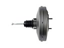 2006 Dodge Caravan Brake Booster
 2006 Dodge Caravan Brake Caliper
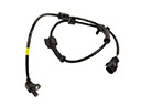 2006 Dodge Caravan Speed Sensor
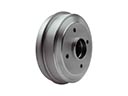 2006 Dodge Caravan Brake Drum
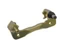 2006 Dodge Caravan Brake Caliper Bracket
 2006 Dodge Caravan Brake Disc
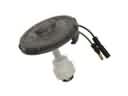 2006 Dodge Caravan Brake Fluid Level Sensor
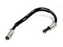 2006 Dodge Caravan Brake Line
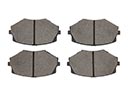 2006 Dodge Caravan Brake Pad
 2006 Dodge Caravan Hydraulic Hose
 2006 Dodge Caravan Parking Brake Shoe
 2006 Dodge Caravan Wheel Stud