JeepParts
My Garage
My Account
Cart
OEM Chrysler 300M Axle Shaft
Car Axle Shaft- Select Vehicle by Model
- Select Vehicle by VIN
Select Vehicle by Model
orMake
Model
Year
Select Vehicle by VIN
For the most accurate results, select vehicle by your VIN (Vehicle Identification Number).
4 Axle Shafts found

Chrysler 300M Axle Assembly, Front Driver Side Part Number: 4882517
$125.95 MSRP: $578.00You Save: $452.05 (79%)Ships in 1-2 Business DaysChrysler 300M Axle Assembly, Front Driver Side Part Number: 5074003AA
Chrysler 300M Axle Assembly, Front Part Number: 5074002AA
Chrysler 300M Axle Assembly, Front Passenger Side Part Number: 4882518
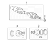
Chrysler 300M Axle Shaft
Choose OEM Axle Shaft that meet Chrysler factory standards. Chrysler designs and tests every component for precision and durability. Each Axle Shaft follows strict manufacturing steps to lock in quality and fit. If your Chrysler 300M matters to you, OEM parts make the smart choice. You'll get the exact look, feel, and performance you expect. Shop genuine 300M parts at the highly competitive prices online. Enjoy a manufacturer's warranty, a hassle-free return policy, and rapid delivery. No more guesswork with off brands. Get genuine parts with exact fit and true factory performance. Shop with confidence today at JeepPartsDeal.com.
The Axle Shaft is one of the main components of the vehicle that greatly affects its dependability and capability. Intended to help shift power from the differential to the drive wheels, 300M Axle Shaft is independent of the other hence can turn the wheels in one manner while the other turns in another in a bid to achieve better road traction when cornering and enhancing the general handling of the wheels. Made of steel, this Axle Shaft is suited to wide varieties of loads while on duty and offers durability and reliable service. It is relevant to be compatible with several types of 300M cars such as the 300M Special Edition and the Pro-Am series and demonstrates the car's flexibility in the Chrysler range. The synthesis of the 300M Axle Shaft contributes in increasing the power and acceleration of the vehicle while at the same time providing the much needed safety by keeping the car in its correct position while in motion. Significantly, the 300M Axle Shaft provided with splined ends that mate directly on the differential and wheel hub for efficient power transfer in the independent suspension system. This design eliminates or lessens the effects of noise and vibrations which may be caused by depreciation of the components. Axle Shaft holds strong market reputation in the automobile industry owing to its application for increasing the mechanical efficiency and safety of cars, therefore it becomes a reliable product for Chrysler users looking for strong and reliable 300M Axle Shafts.
Chrysler 300M Axle Shaft Parts and Q&A
- Q: How to Remove and Install an Axle Shaft on Chrysler 300M?A:Raise the vehicle on jackstands or a frame contact type hoist and then remove the front wheel and tire assembly to access the halfshaft. Following that, free the front caliper from the knuckle and pull the front braking disk off the wheel mounts. Take away the speed sensor cable routing bracket from both the strut end and the hub and bearing-to-stub axle nut. Remove the inner tripod joint from the transaxle cubby by prying on the tripod joint with a pry bar that has been slipped between the transaxle case and the joint, making sure not to release it from the transmission stub shaft at this time. Before removing the strut assembly, turn the nuts away from the bolts but keep the bolts straight in the Steering Knuckle to stop possible damage. Unscrew the strut assembly to the steering knuckle attaching bolts and undo the strut assembly from the top end of the steering knuckle. Below the suspension extension, take the outer C/V joint assembly in your hand and move the steering knuckle outward and rearward until the outer C/V joint clears the hub and bearing. The inner tripod joint and interconnecting shaft should be both grasped and pulled on together to remove the driveshaft from the transaxle stub shaft. Place the original O-ring seal and the joint retaining circlip on the stub shaft and next, run a bead of grease evenly around the joint's spline. Push the driveshaft through the hole of the splash shield, aligning its inner tripod spline with the stub shaft spline from the transaxle and rock the driveshaft back and forth to get the circlip over it. Pull the tripod joint all the way onto the stub shaft, so that when it is fully installed, you can't see the O-ring seal. To confirm that the inner tripod joint retaining circlip is properly locked, try moving the joint; if it sticks, then it's locked. Be careful not to scratch, bend or push the flinger disk out of shape while you install the outer C/V joint. Turn the steering knuckle as you hold the outer C/V joint assembly to put the outer C/V joint into its place on the hub and bearing. Set the top of the steering knuckle into the strut assembly, make sure holes match and correctly place the strut assembly onto the top of the steering knuckle attaching bolts, tightening the nuts to 210 Nm (155 ft. lbs.) without turning the bolts. Mount a fresh retaining nut onto the hub and inner bearing part of the stub shaft, tighten it without torqueing at the moment. Put the speed sensor cable routing bracket on the strut assembly in the front and firmly tighten the routing bracket screw. Place the brake disk on the hub and bearing assembly and install the front caliper over the brake disk, making sure the caliper holes are aligned with those on the steering knuckle. Hold it there and tighten all of the caliper bolts to 22 Nm (192 inch lbs.). When you are ready, put the wheel and tire assembly on the vehicle, secure with nuts, tighten them half specification at first, then repeat to the full specified torque of 135 Nm (100 ft. lbs.) and let the vehicle down from the lift or stands. Applying the brakes, set the new stub shaft to hub and bearing assembly retaining nut to 142 Nm (105 ft. lbs.), making sure you do not apply more torque than stated to protect the driveshaft.
- Q: How to Service an Axle Shaft on Chrysler 300M?A:First, lift the car off the ground using jackstands or a frame contact type hoist, then remove the front wheel and tire. Remove the front assembly from the front Steering Knuckle and pull the front disk straight off the wheel mounting studs. After that, remove the speed sensor cable bracket from the strut assembly and pull the hub and bearing off the surface where it is fastened to the stub axle retaining nut. Secure Puller, Special Tool 6790, on the hub and bearing assembly by using whell lug nuts. Screw on a needle lug nut to cover the threads on the wheel stud before prying around the outside edge of the hub with a flat blade tool. Insert a pry bar between the transaxle case and the inner tripod joint to take the inner tripod joint away from the stub shaft retaining snap ring. Untwist the attachment bolts holding the strut assembly to the steering knuckle and pull out the top of the steering knuckle. Grab the outer C/V joint assembly and swing the steering knuckle in a circle until the end of the outer C/V joint clears the hub and bearing assembly. Take the tripod joint off the transaxle stub shaft without using force on the connecting shaft to prevent separating the spider from the tripod housing. First, fit a new O-ring seal and the circlip around the stub shaft. Then, add a thin line of grease to the spline on the inner tripod joint, making sure it's even and where the O-ring sits. Place the driveshaft through where the splash shield has a hole, fit the inner tripod joint end onto the stub shaft at the transaxle, then use movement from side to side to slide past the circlip. Put the tripod joint onto the stub shaft until it doesn't move, so the O-ring remains hidden. Check the circlip's lock by pulling the inner tripod joint; if tight, the joint will not move. After fixing the C/V joint to the hub and bearing, position the top section of the steering knuckle right over the mounting holes on the strut assembly. Screw the steering knuckle attaching bolts into the strut, tightening the nuts to 169 Nm (125 ft. lbs.), while avoiding twisting the bolts in the steering knuckle. Place a new retaining nut on the hub and bearing assembly connected to the stub shaft. Tighten the nut for now, without using torque. Attach the speed sensor cable bracket back in place and put the braking disk onto both the hub and the bearing assembly. Place the Brake Caliper in front of the braking disk, connecting the caliper with the fork's mounting holes as you tighten the caliper to steering knuckle bolts using 19 Nm (168 inch lbs.). Next, fit the wheel and tire assembly, tightening each wheel mounting stud nut as described in the right sequence to a torque of 129 Nm (95 ft. lbs.). Then, lower the car, apply the brakes to hold it in place and tighten the new stub shaft to hub and bearing assembly retaining nut fully to 150 Nm (105 ft. lbs.), taking care not to over-torque.

Related Chrysler 300M Parts
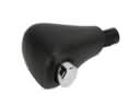 Chrysler 300M Automatic Transmission Shift Levers
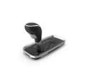 Chrysler 300M Automatic Transmission Shifter
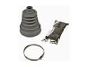 Chrysler 300M CV Boot
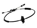 Chrysler 300M Shift Cable
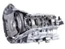 Chrysler 300M Transmission Assembly
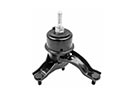 Chrysler 300M Transmission Mount
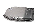 Chrysler 300M Transmission Pan
Browse Chrysler 300M Axle Shaft by Years
2004 2003 2002 2001 2000 1999