JeepParts
My Garage
My Account
Cart
OEM Dodge Caravan Steering Knuckle
Front Steering Knuckle- Select Vehicle by Model
- Select Vehicle by VIN
Select Vehicle by Model
orMake
Model
Year
Select Vehicle by VIN
For the most accurate results, select vehicle by your VIN (Vehicle Identification Number).
7 Steering Knuckles found


Dodge Caravan Knuckle, Front Driver Side Part Number: 4694953AB
$502.96 MSRP: $614.00You Save: $111.04 (19%)Ships in 1-2 Business Days
Dodge Caravan Knuckle, Front Part Number: 4694822
$360.81 MSRP: $457.39You Save: $96.58 (22%)Ships in 1-2 Business Days


Dodge Caravan Knuckle, Front Passenger Side Part Number: 4694952AB
Dodge Caravan Knuckle, Front Part Number: 5015935AA
Dodge Caravan Knuckle, Front Part Number: 5015934AA
Dodge Caravan Knuckle, Front Part Number: 4694823

Dodge Caravan Knuckle Part Number: 4449458
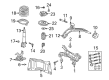
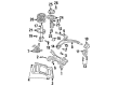
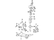
Dodge Caravan Steering Knuckle
Choose OEM Steering Knuckle that meet Dodge factory standards. Dodge designs and tests every component for precision and durability. Each Steering Knuckle follows strict manufacturing steps to lock in quality and fit. If your Dodge Caravan matters to you, OEM parts make the smart choice. You'll get the exact look, feel, and performance you expect. Shop genuine Caravan parts at the highly competitive prices online. Enjoy a manufacturer's warranty, a hassle-free return policy, and rapid delivery. No more guesswork with off brands. Get genuine parts with exact fit and true factory performance. Shop with confidence today at JeepPartsDeal.com.
The Steering Knuckle in Dodge Caravan is pivotal that enhances the link between the suspension and the steering assembly of the car to the front wheels. It features threaded holes to support control arms, tie-rod ends and spindle or hub, therefore allows the suspension system to move up and down when responding to road surface irregularities and swivel sideways when being steered. There can also be two types depending on the drive type, where front-wheel, all/4-wheel drive Steering Knuckles are different from the rear-wheel drive Steering Knuckles of the Dodge Caravan. The main difference is in the connection between the spindle and hub, on front-wheel-drive models there is a hub connected to the Steering Knuckle whereas on rear-wheel- drive the models may contain an integrated spindle.
Dodge Caravan Steering Knuckle Parts and Q&A
- Q: How to Service and Repair a Steering Knuckle on Dodge Caravan?A:Service or repair the steering knuckle by raising the car, supporting it and then taking off the wheel and tire. After that, remove the cotter pin, nut loop and spring washer from the stub axle and hub nut. Let a helper press the brake pedal to keep the hub from rotating as you remove the nut holding it in place. Take the disc Brake Caliper and adapter off the side of the knuckle so there's no tension on the brake hose. Hold onto the Tie Rod End stud and use a wrench to detach the nut joining the outer tie rod end to the steering knuckle. Eliminate the tie rod end out of the steering knuckle by applying Special Tool C-3894-A. If the vehicle comes with antilock brakes, get the front wheel speed sensor out from the steering. With two bolts removed from the steering knuckle to the strut clevis bracket, tilt the knuckle outwards and pull the stub axle from the hub and bearing, leaving the driveshaft hanging. Put the impact wrench on the ball joint nut and unscrew it and ensure the new nut is even with the top of the ball joint stud when you replace it. With Special Tool C-4150A, undo the ball joint stud from the knuckle and then remove the top nut, then pull the steering knuckle out of the vehicle. If required, remove the four bolts that link the hub and bearing to the knuckle. When you spot cracks, dents or stress in the knuckle, it should be replaced. If the hub and bearing go in the knuckle, align them with the four threaded holes and secure with bolts at 65 Nm (45 ft. lbs.). Be sure to wipe the design location for the knuckle on the ball joint first. Attach the new steering knuckle to the ball joint stud nut, fixing it to a torque of 81 Nm (60 ft. lbs.) as you hold the stud still. Put the driveshaft stub axle into the hub and bearing and check that you have not rotated the bolts used to join the steering knuckle to strut assembly while installing. Secure the steering knuckle to the clevis bracket of the strut damper assembly, using the attaching bolts to a torque setting of 81 Nm (60 ft. lbs.) and then turning them one more 1/4 rotation. Slip the tie rod end onto the steering arm, start adding the nut to the stud and tighten it to 75 Nm (55 ft. lbs.). Install the wheel speed sensor on the rotor and tighten the bolt to 7 Nm (0.0 inch lbs.) only if your car comes with antilock brakes. Make sure the brake rotor is on the hub and bearing assembly, then fit on the disc brake caliper and adapter. Tighten the adapter's mounting bolts to 169 Nm (125 ft. lbs.). Wash away any dirt or grime from around the stub axle joint, then attach the washer and hub nut, making sure the hub nut is tightened to 244 Nm (180 ft. lbs.) as your assistant brakes the brakes. Set up the spring wave washer, the hub nut lock and a replaced cotter pin, keeping the prongs securely around the lock nut. Re-connect the wheel and tire using the original sequence, but only tighten the bolts to half of what's required at first, then repeat the process by tightening them all to the full 135 Nm (100 ft. lbs.). Following that, adjust the vehicle's height and check the front wheel alignment camber and toe as you see fit.
- Q: How to Maintain and Fix a Steering Knuckle on Dodge Caravan?A:Before fixing or repairing the steering knuckle, lift the car up on jack stands or use a frame contact type hoist. Take out the cotter pin, nut lock and the wheel and tire assembly from the stub axle. Unscrew the hub nut and remove the wave washer from the stub axle, checking that the vehicle doesn't roll or stand on the tires so you don't damage the Wheel Bearings. After braking the vehicle, take out the stub axle by removing the hub nut, then separate the two front disc Brake Caliper to steering knuckle bolts. Next, pry the top of the caliper away from the knuckle and draw the bottom out below the machined abutment. Fix a wire hook under the brake assembly so that you do not apply pressure to the brake flex hose and then remove the brake rotor from the hub and bearings. After holding the Tie Rod End stud with a 11/32 socket, use a wrench to remove the outer tie rod nut and then Remover, Special Tool MB-991113, to unfasten the tie rod end from the steering knuckle. First, remove the front wheel Speed Sensor and (if your car has one) the wheel stop from the steering knuckle and then install the pinch bolt from the rear so it faces the front during reassembly. Release the steering knuckle from the ball joint stud, clamping nut and bolt by taking the stud out with a pry bar. Be careful not to tear up the ball joint seal or come apart the inner C/V joint. Before taking the steering knuckle off the strut, separate the steering knuckle from the outer C/V joint and unscrew the two steering knuckle to clevis bracket bolts. If you're moving these parts, take out the four bolts holding the hub and bearing to the knuckle. Should the installation involve inserting the hub and bearing into the knuckle, secure them and close them with four tightened bolts to 65 Nm (45 ft. lbs.). When the steering knuckle to strut assembly is installed, remember not to turn the attaching bolts and if eccentric bolts are provided, set them on the bottom hole in the strut clevis bracket. Charge the steering knuckle in the clevis bracket, affix the strut damper to the bolts and turn them in to 90 Nm (65 ft. lbs.) plus an extra 1/4 turn. Return the drive shaft into the front hub then mount the steering knuckle onto the ball joint assembly, secured by the stud. Put in a new steering knuckle, ball joint stud, clamping bolt and nut. Torque these parts to 145 Nm (105 ft. lbs.). Fit the tie rod on the steering knuckle, keep the stud stationary with an 11/32 socket and tighten the nut by 54 Nm (40 ft. lbs.). Attach the hub and bearing assembly to the Brake Disc, then the disc brake caliper assembly, making sure the lowest end is pressed up under the abutment before you rotate the top over it. Screw the securing bolts of the caliper assembly to 22 Nm (195 inch lbs.). Clean the threads where the C/V joint connects to the rear C/V stub axle, add the washer and nut and tighten good and tight. Place the wheel speed sensor back into position and secure it tight with a torque wrench set to 7 Nm (60 inch lbs.) and then fit the front wheel and tire. Tighten each stud nut sequentially to 135 Nm (100 ft .lbs.). Reduce the height of your car and, after braking it, tighten the hub nut to 244 Nm (180 ft. lbs.). After that, fit the spring wave washer to the stub axle, the hub nut lock and insert a fresh cotter pin while tightening the prongs around the hub nut lock. Now, set the front toe to the appropriate specification.


Related Dodge Caravan Parts
 Dodge Caravan Axle Beam Mount
 Dodge Caravan Axle Pivot Bushing
 Dodge Caravan Axle Support Bushings
 Dodge Caravan Ball Joint
 Dodge Caravan Control Arm
 Dodge Caravan Control Arm Bushing
 Dodge Caravan Crossmember Bushing
 Dodge Caravan Shock Absorber
 Dodge Caravan Shock And Strut Mount
 Dodge Caravan Sway Bar Bracket
 Dodge Caravan Sway Bar Bushing
 Dodge Caravan Sway Bar Link