JeepParts
My Garage
My Account
Cart
OEM Dodge Journey Ball Joint
Control Arm Joint- Select Vehicle by Model
- Select Vehicle by VIN
Select Vehicle by Model
orMake
Model
Year
Select Vehicle by VIN
For the most accurate results, select vehicle by your VIN (Vehicle Identification Number).
1 Ball Joint found


Dodge Journey Lower Ball Joint, Front Part Number: 5090033AB
$53.36 MSRP: $76.70You Save: $23.34 (31%)
Dodge Journey Ball Joint
Choose OEM Ball Joint that meet Dodge factory standards. Dodge designs and tests every component for precision and durability. Each Ball Joint follows strict manufacturing steps to lock in quality and fit. If your Dodge Journey matters to you, OEM parts make the smart choice. You'll get the exact look, feel, and performance you expect. Shop genuine Journey parts at the highly competitive prices online. Enjoy a manufacturer's warranty, a hassle-free return policy, and rapid delivery. No more guesswork with off brands. Get genuine parts with exact fit and true factory performance. Shop with confidence today at JeepPartsDeal.com.
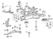
This part is called the Ball Joint and is crucial in the functionality of the Dodge Journey, a practical and safe crossover vehicle. It is a ball joint that links the control arms to the steering knuckles for rotation as well as preventing other undesirable motions that are dangerous to the car's stability. Made of steel and sheathed by a boot, this Ball Joint is highly reliable, long-lasting, and functional for many of the Dodge Journey models. Thus, the compatibility with various versions of the Dodge Journey augments its effectiveness and reliability within the front suspension framework. The Dodge Journey that features a large interior space and executes safety features helps from lossy ball joint improving managing and comfort of the ride. Notably however, the Ball Joint offers an adjustment of caster and camber for optimal and superior driving experience. This feature coupled with a reliable braking system on the Journey makes it safe for families and individuals on the road. As the Dodge Journey model was thankfully terminated in 2020, its tradition of comfort, safety, and affordability can be considered everlasting; moreover, the Ball Joint remains an acclaimed invention of the automotive industry because of its function in a vehicle's performance and endurance.
Dodge Journey Ball Joint Parts and Q&A
- Q: How to Install a Ball Joint in the Front Suspension on Dodge Journey?A:First, hold Remover/Installer 8441-1 and use Installer 9964-1 and Installer 9964-2 with the ball joint stem down in Installer 9964-2. Set up the assembly next to the knuckle and rotate the screw-drive by hand. Next, attach a hand-tool to the screw-drive and tighten it to push the ball joint into the knuckle until you feel the flange against the bottom of the knuckle. Loose the screwdriver and pop out the tools. Following that, use a drift punch to set the snap-ring in the groove of the ball joint. Press the hub and bearing in the knuckle onto the splines found on the half shaft outer C/V joint. Insert the lower ball joint stud into the Control Arm's hole and put the new nut on, tighten it to 95 Nm (70 ft. lbs.). First, hold the wheel speed sensor head in place inside the knuckle, secure it with a 12 Nm (106 in. lbs.) tightened mounting screw and then attach the routing clip to secure the wheel speed sensor's cable to the knuckle. Next, fit the brake rotor, add the disc Brake Caliper and adapter and always use a new hub nut because the original is only good for one use. Work on the threads of the half shaft outer C/V joint, then thread and tighten the hub nut on the shaft's end. After your assistant presses the brakes to stop the hubs, use 132 Nm (97 ft. lbs.) to tighten the hub nut. Slide the tire and wheel unit in place, then tighten the nuts on the wheel to 135 Nm (100 ft. lbs.). After that, lower the vehicle and carry out alignment for the wheels.

Related Dodge Journey Parts
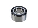 Dodge Journey Wheel Bearing
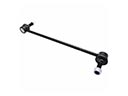 Dodge Journey Sway Bar Link
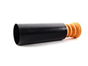 Dodge Journey Bump Stop
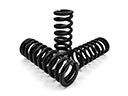 Dodge Journey Coil Springs
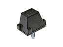 Dodge Journey Control Arm Bumper
 Dodge Journey Lateral Link
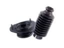 Dodge Journey Shock and Strut Boot
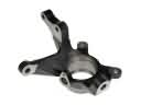 Dodge Journey Steering Knuckle
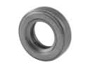 Dodge Journey Strut Bearing
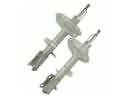 Dodge Journey Strut Housing
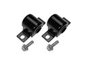 Dodge Journey Sway Bar Bushing
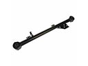 Dodge Journey Trailing Arm