JeepParts
My Garage
My Account
Cart
OEM Dodge Viper Steering Column
Steering Column Tilt- Select Vehicle by Model
- Select Vehicle by VIN
Select Vehicle by Model
orMake
Model
Year
Select Vehicle by VIN
For the most accurate results, select vehicle by your VIN (Vehicle Identification Number).
5 Steering Columns found

Dodge Viper Steering Column Part Number: 4642805
$109.43 MSRP: $138.73You Save: $29.30 (22%)Ships in 1-2 Business Days
Dodge Viper Steering Column Part Number: 4865679AC
$415.81 MSRP: $499.00You Save: $83.19 (17%)Ships in 1-3 Business Days

Dodge Viper Steering Column Part Number: 68159858AB
$327.44 MSRP: $482.00You Save: $154.56 (33%)Dodge Viper Steering Column Part Number: 68262523AC
$415.64 MSRP: $605.00You Save: $189.36 (32%)
Dodge Viper Steering Column Part Number: 4874334AB
Dodge Viper Steering Column
Choose OEM Steering Column that meet Dodge factory standards. Dodge designs and tests every component for precision and durability. Each Steering Column follows strict manufacturing steps to lock in quality and fit. If your Dodge Viper matters to you, OEM parts make the smart choice. You'll get the exact look, feel, and performance you expect. Shop genuine Viper parts at the highly competitive prices online. Enjoy a manufacturer's warranty, a hassle-free return policy, and rapid delivery. No more guesswork with off brands. Get genuine parts with exact fit and true factory performance. Shop with confidence today at JeepPartsDeal.com.
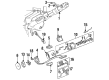
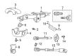
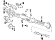
The Dodge Viper's Steering Column is part and parcel of the very fabric of this prime and quite well-known muscle car that is designed and built to deliver spectacular performance and reliability ratings. This is an important subassembly which interconnects the steering wheel to the steering gear in order to translate the steering angles and the corresponding torques with great clarity to the vehicle's response. The Dodge Viper Steering Column is another component, and it is equipped with safety characteristics; it is collapsible for the sake of dispersing the shock load upon impact and protecting the driver. Also, it comes with universal joints that control the movements; this makes impacts more safe and secure. This Steering Column applies to a number of Viper generations, so each model of Dodge Viper is enhanced by this sophisticated technology. Besides their main role, the Steering Columns also provide support for installing other components, switches, and gauges, therefore improving a car's performance. The Dodge Viper Steering Column meets all federal standards concerning installations of anti theft and safety features that improve security in the car. Indeed, based on the model's construction and design, the Dodge Viper stands out on the automobile market, thus strengthening the identify of the car as one of the iconic American automobiles. Still, talking about the basic car components, the Dodge Viper Steering Column is not only a sound and reliable part, but also one of the most important and unique parts which makes the Dodge Viper a legend of the car roads.
Dodge Viper Steering Column Parts and Q&A
- Q: How is the Steering Column Installed on Dodge Viper?A:Before installing the steering column, set the Ignition Switch to ON if it needs to happen while powered on. Fit the shaft (2) through the ignition switch by pushing the end with the taper onto it. Hold the switch in place with screw (1). Slide the end of the halo lamp onto the factory harness, snapping the tabs into the ignition cylinder housing. Place the multi-function/windshield wiper switch on the column and attach it with two screws. Place the small Clock Spring onto the end of the column and put the latch hooks into the column. Position the ignition key cylinder in the ON direction, insert it into the ignition cylinder housing until the retaining tab (2) locks and then release the key cylinder. Drill the small holes for the steering column, then attach the steering column bases into the opening for the column, fitting the mounting brackets with studs and use two lower nuts to hold it. Join the wiring harness electrical connectors (1, 2, 3) to the multi-function switch, windshield wiper switch and ignition switch and hook connector 3 up to the Clock Spring (2). Position the column correctly, then assemble two upper support nuts and tighten all four to 17 Nm (150 in. lbs.). Place both front wheels entirely straight ahead and turn the shaft of the steering column until its missing spline area is level with the other splines on the intermediate shaft extension (5) coupling. Couple the intermediate shaft extension (5) onto the shaft of the steering column (3), put the pinch bolt through it and tighten using 49 Nm (36 ft. lbs.). Place the upper and lower shrouds (4 and 8) around the steering column. Join the upper section to the lower, secure them with screws and they should click together. Before fitting the Steering Wheel, line up the Clock Spring so it doesn't touch the top of the shaft; after that, push the steering wheel onto the column, position its spline where the missing spline is and make sure no part of the Clock Spring is blocked. Secure the steering wheel retaining bolt and tighten it by 54 Nm or 40 ft. lbs. Plug the connector from the horn switch (2) into the driver air bag (1) and join the squib wires (6) by the color codes and push them in until you hear a click. Put the squib wiring routing clips (3, 4) on the steering wheel, place the driver air bag where necessary, then screw in three air bag brackets, tightening them to 12 Nm (105 in. lbs.) Put the lower instrument panel Steering Column Cover into place. After completing the air bag System Test, join the battery ground terminal again, check all parts of the steering column, restore the radio and clock settings, check the tilt adjustments and follow a road test to check the steering system.

Related Dodge Viper Parts
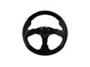 Dodge Viper Steering Wheel
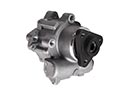 Dodge Viper Power Steering Pump
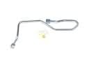 Dodge Viper Power Steering Hose
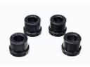 Dodge Viper Rack & Pinion Bushing
 Dodge Viper Rack And Pinion
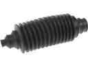 Dodge Viper Rack and Pinion Boot
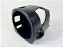 Dodge Viper Steering Column Cover
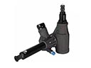 Dodge Viper Steering Gear Box
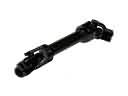 Dodge Viper Steering Shaft
 Dodge Viper Tie Rod Bushing
 Dodge Viper Tie Rod End
 Dodge Viper Upper Steering Column Bearing
Browse Dodge Viper Steering Column by Years
2017
2016
2015
2010
2009
2008
2006
2005
2004
2003
2002
2001
2000
1999
1998
1997
1996
1995
1994
1993
1992