JeepParts
My Garage
My Account
Cart
OEM Jeep Commander Rod Bearing
Engine Connecting Rod Bearing- Select Vehicle by Model
- Select Vehicle by VIN
Select Vehicle by Model
orMake
Model
Year
Select Vehicle by VIN
For the most accurate results, select vehicle by your VIN (Vehicle Identification Number).
4 Rod Bearings found


Jeep Commander Bearings Part Number: 5012363AE
$16.87 MSRP: $25.00You Save: $8.13 (33%)Ships in 1-2 Business Days


Jeep Commander Bearings Part Number: 68052222AB
$18.13 MSRP: $26.80You Save: $8.67 (33%)Ships in 1-2 Business Days


Jeep Commander Connecting Rod Bearing Part Number: 68029429AC
$16.02 MSRP: $23.55You Save: $7.53 (32%)Ships in 1-2 Business Days


Jeep Commander Connecting Rod Bearing Part Number: 68207790AA
$6.32 MSRP: $7.70You Save: $1.38 (18%)
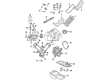
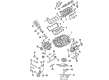
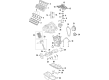
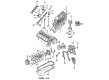
Jeep Commander Rod Bearing
Choose OEM Rod Bearing that meet Jeep factory standards. Jeep designs and tests every component for precision and durability. Each Rod Bearing follows strict manufacturing steps to lock in quality and fit. If your Jeep Commander matters to you, OEM parts make the smart choice. You'll get the exact look, feel, and performance you expect. Shop genuine Commander parts at the highly competitive prices online. Enjoy a manufacturer's warranty, a hassle-free return policy, and rapid delivery. No more guesswork with off brands. Get genuine parts with exact fit and true factory performance. Shop with confidence today at JeepPartsDeal.com.
The Jeep Commander Rod Bearing can be described as a part that makes a large difference between high performing and sturdy Jeep Commander automobiles. Located to bear the force on the crank shaft and connecting rods, the Rod Bearing allows free rotation without much friction on the component, which is vital for the smooth running of the engine. These Rod Bearings come in both bi-metal and tri-metal designs and developed to meet numerous Commander models' needs, ranging from the XK to the 2022 Meridian. There is a bi-metal version that has an aluminum alloy plating as well as a tri-metal model that has a strong copper alloy layer to improve the metal's strength and fatigue. From the description of its functioning, precision machining ensures safety of the shaft's placement within the provided bores to achieve maximum oil clearance for its functionality. Jeep Commander Rod Bearing is another part that matters regarding fuel economy and safety of the car as it drastically decreases the risk of winning the championship in the "engine breakdown" category. By use of technology in coming up with better materials ad coatings, the performance variants of the Rod Bearing are developed to enhance the high output engines with better lubrication and longer durability. Much attention is paid to details in Jeep Commander Rod Bearing, which would place it high in the automotive market since it represents the Jeep brand known for its reliable and high-performing vehicles. It doesn't matter if the roads are urban or challenging, the Jeep Commander Rod Bearing fits perfectly and ensures a steady ship; thus, it fits Jeep enthusiasts perfectly.
Jeep Commander Rod Bearing Parts and Q&A
- Q: What Are the Key Steps to Inspect and Install Rod Bearings on Jeep Commander?A:Check the rod bearings for scoring, examine them for signs of normal wear and check for grooving, fatigue and pitting. Replace any bearing that has unusual wear. Look for scoring, nicks or burrs on the connecting rod journals, since misaligned or bent rods can cause Pistons, piston rings, cylinder walls, connecting rod bearings and Crankshaft connecting rod journals to wear unevenly. When you spot wear or damage showing the rod is out of alignment, check it and replace misaligned, bent or twisted connecting rods. Remove excess oil from the connecting rod journal, cover the top bearing insert with oil and place it in the connecting rod so it is centered. At points A and B, make certain the gap you measure is narrower than 0.50mm (0.0196 inch). Apply compression from a piston ring compressor and the Special Tool 8507 pins to place the rod and piston assemblies, making sure the oil slinger on the rod is near the front and the "F"s on the wrist pin toward the front. Before installing the mains shims, place the lower bearing insert in the cap and center it, then put a strip of Plastigage over the full length of the insert in the bearing cap's center. Insert the bearing cap and connecting rod on the journal and then secure them with bolts torqued to 27 Nm (20 ft. lbs.) plus a 90° turn, without rotating the crankshaft to protect the Plastigage. After taking off the bearing cap, measure the thickness of the compressed Plastigage to check how much the bearing is touching the journal because the bearing-to-journal clearance must fall within the required Engine Specifications. Differences in clearance can be the result of a tapered bearing, a bent connecting rod or something caught between the insert and the cap or rod. When an acceptable clearance is marked, take out the Plastigage and go ahead with installation. If the clearance exceeds the recommendations, find the right barrel set since rods bolts cannot be safely used again and should always be renewed whenever one comes loose or is removed. Repeat the Plastigage measurement, install the chosen bearing when it fits and tighten the connecting rod bolts to 27 Nm (20 ft. lbs.) plus a 90° turn. Pull the engine apart, use a feeler gauge to ensure the side clearance is correct and attach a connecting rod from the replacement kit if it's off by even half a millimeter.

Related Jeep Commander Parts
 Jeep Commander Oil Pan Gasket
 Jeep Commander Camshaft
 Jeep Commander Cylinder Head Gasket
 Jeep Commander Engine Mount
 Jeep Commander Exhaust Valve
 Jeep Commander Harmonic Balancer
 Jeep Commander Lash Adjuster
 Jeep Commander Motor And Transmission Mount
 Jeep Commander Oil Pump
 Jeep Commander Piston
 Jeep Commander Pushrod
 Jeep Commander Timing Cover