JeepParts
My Garage
My Account
Cart
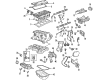
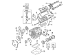
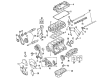
OEM 2002 Chrysler Sebring Rod Bearing
Engine Connecting Rod Bearing- Select Vehicle by Model
- Select Vehicle by VIN
Select Vehicle by Model
orMake
Model
Year
Select Vehicle by VIN
For the most accurate results, select vehicle by your VIN (Vehicle Identification Number).
5 Rod Bearings found


2002 Chrysler Sebring Bearings Part Number: 5174612AA
$14.57 MSRP: $24.10You Save: $9.53 (40%)Product Specifications- Other Name: Bearing - Connecting Rod; Bearing Kit Connecting Rod Standard See Note; Bearing Kit Connecting Rod Standard
- Replaces: 5093448AB, 5012588AA
- Item Weight: 0.50 Pounds
- Item Dimensions: 3.7 x 2.6 x 1.9 inches
- Condition: New
- Fitment Type: Direct Replacement
- SKU: 5174612AA
- Warranty: This genuine part is guaranteed by Mopar's factory warranty.

2002 Chrysler Sebring Bearings Part Number: 68000512AB
$41.06 MSRP: $61.30You Save: $20.24 (34%)Ships in 1-2 Business DaysProduct Specifications- Other Name: Bearing Package - Connecting Rod; Rod Bearing
- Replaces: 4796546AB, 4796546AC, 68000512AA
- Item Weight: 0.50 Pounds
- Item Dimensions: 3.9 x 2.6 x 2.0 inches
- Condition: New
- Fitment Type: Direct Replacement
- SKU: 68000512AB
- Warranty: This genuine part is guaranteed by Mopar's factory warranty.

2002 Chrysler Sebring Bearing Set, Blue Part Number: MD327505
$3.62 MSRP: $4.58You Save: $0.96 (21%)Ships in 1-2 Business DaysProduct Specifications- Other Name: Bearing - Connecting Rod; Bearings; Bearing Connecting Rod S3
- Item Weight: 0.50 Pounds
- Condition: New
- Fitment Type: Direct Replacement
- SKU: MD327505
- Warranty: This genuine part is guaranteed by Mopar's factory warranty.
2002 Chrysler Sebring Bearing Set Part Number: 1115A106
Product Specifications- Other Name: Bearing - Bearing, Connecting Rod; Rod Bearing; Bearings
- Replaces: MD327504
- Item Weight: 1.10 Pounds
- Condition: New
- Fitment Type: Direct Replacement
- SKU: 1115A106
- Warranty: This genuine part is guaranteed by Mopar's factory warranty.
2002 Chrysler Sebring Bearing Set, Yellow Part Number: 1115A105
Product Specifications- Other Name: Bearing - Connecting Rod; Rod Bearing; Bearings
- Item Weight: 0.40 Pounds
- Item Dimensions: 3.9 x 2.3 x 1.0 inches
- Condition: New
- Fitment Type: Direct Replacement
- SKU: 1115A105
- Warranty: This genuine part is guaranteed by Mopar's factory warranty.
2002 Chrysler Sebring Rod Bearing Parts and Q&A
- Q: What Precautions Are Essential for Proper Rod Bearing Installation to Prevent Engine Damage on 2002 Chrysler Sebring?A: Fit the entire bank with connecting rods, but // notice their bearing caps are not interchangeable and should be marked when removed. It is critical to prevent damaging the fractured rod and cap joint surfaces, since damage here can lead to engine problems. Make sure the upper half of the bearings has its hole over the oil squirt opening before you insert the bearings and caps and make sure the tangs are placed on the same side as the rods for the caps. Both holes in the engine must be properly aligned to stop damage to the engine. Only 0.015 mm (0.0006 inch) of taper or out-of-round is acceptable on any crankshaft journal and bearings are available throughout the industry in 0.025 mm (0.001 inch) and 0.250 mm (0.010 inch) undersize varieties. Use the bearings two at a time, so the old part doesn't mix with the new one and make sure not to file the rods or bearing caps. You can use plastigage when measuring Main Bearing Clearance and Connecting Rod Bearing Clearance. Before reusing the connecting rod bearing cap bolts, confirm that their threads haven't been affected by stretching; change any bolt that is damaged. Slight pressure holds the connecting rod bolt in its cap, so when you need to replace them, use a hammer and punch to drive out the bolts from the cap, making sure not to damage the cap. Make sure all the threads on connecting rod bolts contact a straight edge and if not, swap them out. Before inserting the bolts, run some engine oil along the threads, then put them in finger-tight, alternate tightening each nut as you go and finally tighten each nut to the proper setting. To check the clearance on the connecting rod side, anchor a dial indicator to a fixed spot on the engine, point the probe at the connecting rod cap being checked, move the connecting rod all the way back, zero the dial and move the connecting rod forward to the end of its stroke before reading the indication. Line up the measurement with the length specified under engine specifications for each rod and use the crankshaft to reach them all.
Related 2002 Chrysler Sebring Parts
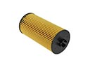 2002 Chrysler Sebring Oil Filter
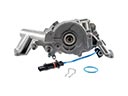 2002 Chrysler Sebring Oil Pump
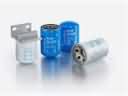 2002 Chrysler Sebring Coolant Filter
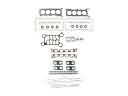 2002 Chrysler Sebring Cylinder Head Gasket
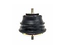 2002 Chrysler Sebring Engine Mount
 2002 Chrysler Sebring Harmonic Balancer
 2002 Chrysler Sebring Intake Valve
 2002 Chrysler Sebring Lash Adjuster
 2002 Chrysler Sebring Oil Filler Cap
 2002 Chrysler Sebring Piston Ring Set
 2002 Chrysler Sebring Timing Chain Guide
 2002 Chrysler Sebring Timing Cover Gasket