JeepParts
My Garage
My Account
Cart
OEM 2005 Dodge Dakota Rocker Arm
Engine Rocker Arm- Select Vehicle by Model
- Select Vehicle by VIN
Select Vehicle by Model
orMake
Model
Year
Select Vehicle by VIN
For the most accurate results, select vehicle by your VIN (Vehicle Identification Number).
1 Rocker Arm found


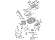
2005 Dodge Dakota Rocker Arms Part Number: 53020742AC
$18.24 MSRP: $26.70You Save: $8.46 (32%)Product Specifications- Other Name: Arm - Valve; Rocker Arm; Rocker Arm Valve
- Replaces: 68045794AA, 53021913AB, 53020742AB
- Item Weight: 0.60 Pounds
- Item Dimensions: 1.8 x 2.6 x 3.7 inches
- Condition: New
- Fitment Type: Direct Replacement
- SKU: 53020742AC
- Warranty: This genuine part is guaranteed by Mopar's factory warranty.
2005 Dodge Dakota Rocker Arm Parts and Q&A
- Q: How to Service a Rocker Arm Assembly on 2005 Dodge Dakota?A: Before servicing the rocker arm assembly, remember to disconnect the negative battery cable to stop any accidental accidental starter. Take off the cover from the cylinder head. To take out the rocker arm for cylinder No. 4, turn the crankshaft until No. 1 is on the bottom of its intake stroke. While holding the rotate button, go clockwise until cylinder No. 1 reaches the BDC combustion position. For cylinders No. 3 and No. 5, turn the crankshaft until cylinder No. 1 nears the point where its piston is furthest up. To start cylinder No. 2 or No. 6, first move the crankshaft so that cylinder No. 1 reaches TDC for its ignition stroke. Press the rocker arm down with the special Tool 8516 Rocker Arm Remover to remove it over the valve spring. When you are ready to attach the rocker arm, pump Tool 8516 downward on the valve spring, making sure the concave pocket is set over the lash adjusters to avoid harm. Before installing the rocker arms, coat them with clean engine oil. Before you fit the rocker arm, move the crankshaft clockwise until cylinder No. 1 reaches BDC intake stroke. To measure cylinder No. 1, rotate the crankshaft until No. 1 is at the position shown as BDC on the combustion stroke. For cylinders No. 3 and No. 5, crank the engine to get cylinder No. 1 to its top-dead-center exhaust position. Turn the crankshaft until cylinder No. 1 reaches top dead center ignition stroke for both cylinders No. 2 and No. 6. Until now, we have taken the cylinder head apart and replaced all of its components. Now it's time to install the cylinder head cover.
Related 2005 Dodge Dakota Parts
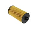 2005 Dodge Dakota Oil Filter
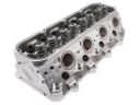 2005 Dodge Dakota Cylinder Head
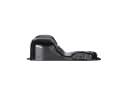 2005 Dodge Dakota Oil Pan
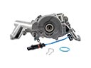 2005 Dodge Dakota Oil Pump
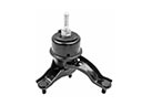 2005 Dodge Dakota Transmission Mount
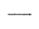 2005 Dodge Dakota Camshaft
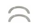 2005 Dodge Dakota Crankshaft Thrust Washer Set
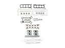 2005 Dodge Dakota Cylinder Head Gasket
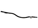 2005 Dodge Dakota Dipstick Tube
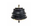 2005 Dodge Dakota Engine Mount
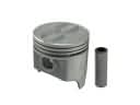 2005 Dodge Dakota Piston
 2005 Dodge Dakota Piston Ring Set