JeepParts
My Garage
My Account
Cart
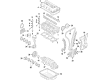
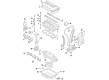
OEM 2008 Dodge Caliber Crankshaft
Crank Shaft- Select Vehicle by Model
- Select Vehicle by VIN
Select Vehicle by Model
orMake
Model
Year
Select Vehicle by VIN
For the most accurate results, select vehicle by your VIN (Vehicle Identification Number).
4 Crankshafts found

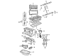
2008 Dodge Caliber Crankshaft Part Number: 68001692AC
Product Specifications- Other Name: Crankshaft - Engine
- Replaces: 4884742AB, 68001692AA
- Item Weight: 50.00 Pounds
- Item Dimensions: 28.6 x 8.2 x 8.4 inches
- Condition: New
- Fitment Type: Direct Replacement
- SKU: 68001692AC
- Warranty: This genuine part is guaranteed by Mopar's factory warranty.

2008 Dodge Caliber Crankshaft Part Number: 68045351AB
Product Specifications- Other Name: Crankshaft - Engine; Crankshaft Package Engine
- Replaces: 68045351AC, 68045351AA
- Item Weight: 45.70 Pounds
- Item Dimensions: 27.8 x 9.5 x 8.1 inches
- Condition: New
- Fitment Type: Direct Replacement
- SKU: 68045351AB
- Warranty: This genuine part is guaranteed by Mopar's factory warranty.

2008 Dodge Caliber Crankshaft Part Number: 68001694AC
Product Specifications- Other Name: Crankshaft - Engine; Crankshaft Kit Engine See Note; Crankshaft Package Engine; Crankshaft Kit Engine
- Replaces: 68001694AA, 4884563AC
- Item Weight: 44.60 Pounds
- Item Dimensions: 21.9 x 8.4 x 7.8 inches
- Condition: New
- Fitment Type: Direct Replacement
- SKU: 68001694AC
- Warranty: This genuine part is guaranteed by Mopar's factory warranty.

2008 Dodge Caliber Crankshaft Part Number: 68001693AC
Product Specifications- Other Name: Crankshaft - Engine; Crankshaft Package Engine; Crankshaft Kit Engine
- Replaces: 4884561AC, 68001693AA
- Item Weight: 42.70 Pounds
- Item Dimensions: 22.3 x 8.4 x 7.7 inches
- Condition: New
- Fitment Type: Direct Replacement
- SKU: 68001693AC
- Warranty: This genuine part is guaranteed by Mopar's factory warranty.
2008 Dodge Caliber Crankshaft Parts and Q&A
- Q: What Are the Steps Involved in Installing a Crankshaft on 2008 Dodge Caliber?A: The crankshaft is secured by five main bearings and all the upper bearing shells inside the crankcase contain grooves and holes for oil, while the lower shells are plain. The lock for crankshaft end play is provided by a two-piece thrust bearing on the number three main bearing journal. Initially clean the threads in the main bearing cap bolt holes with Mopar brake parts cleaner and then blow them out with compressed air. Position the upper bearing shells, so the lubrication grooves and oil holes face the holes in the engine block and the bearing tabs are seated correctly. Should the crankshaft be taken away for machine work, it should be balanced with the target ring attached. Clean and dry the crankshaft and target ring using Mopar brake cleaner and compressed air after cleaning. Install the mounting screws for the target ring each time you set up the ammunition, but don't tighten them yet. Install #1 mounting screw first, then engage it with the same and begin tightening all screws, starting with #1, to 13 Nm (110 in-lbs) in sequence. Add just enough trans gel to the thrust bearings and set them in the block as you would like, with their notches toward the crankshaft. Be careful not to put any oil on this part of the frame near the ladder hook because it will ruin the RTV seal there. Make sure the bolt holes in the main bearing cap are free from debris, dry and not damaged before doing the next steps. Insert the main bearing caps into the main bearing caps, being sure to properly fit the bearing tabs into place and insert the whole assembly onto the engine, dry off the threads first and then loosely tighten the main bearing cap screws. Proper alignment of the thrust bearings is achieved by first rotating the crankshaft so the number 4 piston is at TDC, then pushing the crankshaft to its rear limit, forward to its limit and finally propping up an appropriate tool behind the rear crankshaft counterweight. Study the main bolt heads to check what the proper torque is for each type, since there are different specifications among different bolts. Once the bolt heads are correct, set the first torque to 15 Nm (11 ft. lbs.), then increase it to 27 Nm (20 ft. lbs.) and turn it another 45°. When the numbers do not match, use another three-step process: tighten to 15 Nm (11 ft. lbs.), then to 45 Nm (33 ft. lbs.) and lastly rotate 45°. After that, pull out the wedge tool, measure the turning torque at the crankshaft (it should be less than 5.6 Nm or 50 in. lbs.) and inspect the amount of movement in the crankshaft. Install the connecting rod caps and bearings, but do not reuse the connecting rod bolts, then tighten them to 20 Nm + 90° (15 ft. lbs.) + 90°. Fasten the ladder frame assembly, balance shaft module and crankshaft position sensor using the bolt. If the cylinder head has been removed, put it back in place, add the front crankshaft sprocket, timing chain, timing chain front cover and oil pan. Cover the rear and front crankshaft with the oil seals, put the engine mount support bracket in place and add the crankshaft vibration damper. Attach the water pump pulley, drop the engine from its stand and install the rear oil seal on the crankshaft. New bolts should be used to fit the drive plate/flex plate, until they reach 95 Nm (70 ft. lbs.); then, attach the transaxle and tighten the bellhousing bolts to the same level before installing the engine assembly. After that, set a new oil filter into place, top up with engine oil and coolant, start the engine to confirm there aren't any leaks and fit the engine cover.
Related 2008 Dodge Caliber Parts
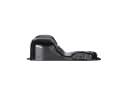 2008 Dodge Caliber Oil Pan
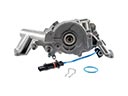 2008 Dodge Caliber Oil Pump
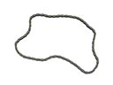 2008 Dodge Caliber Timing Chain
 2008 Dodge Caliber Balance Shaft Chain
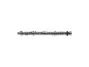 2008 Dodge Caliber Camshaft
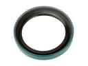 2008 Dodge Caliber Crankshaft Seal
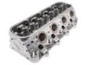 2008 Dodge Caliber Cylinder Head
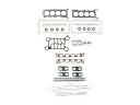 2008 Dodge Caliber Cylinder Head Gasket
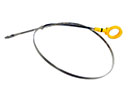 2008 Dodge Caliber Dipstick
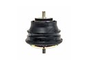 2008 Dodge Caliber Engine Mount
 2008 Dodge Caliber Piston
 2008 Dodge Caliber Timing Chain Guide