JeepParts
My Garage
My Account
Cart
OEM Dodge Caliber Crankshaft
Crank Shaft- Select Vehicle by Model
- Select Vehicle by VIN
Select Vehicle by Model
orMake
Model
Year
Select Vehicle by VIN
For the most accurate results, select vehicle by your VIN (Vehicle Identification Number).
4 Crankshafts found

Dodge Caliber Crankshaft Part Number: 68001693AC

Dodge Caliber Crankshaft Part Number: 68001694AC

Dodge Caliber Crankshaft Part Number: 68045351AB

Dodge Caliber Crankshaft Part Number: 68001692AC
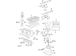
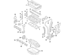
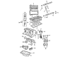
Dodge Caliber Crankshaft
Choose OEM Crankshaft that meet Dodge factory standards. Dodge designs and tests every component for precision and durability. Each Crankshaft follows strict manufacturing steps to lock in quality and fit. If your Dodge Caliber matters to you, OEM parts make the smart choice. You'll get the exact look, feel, and performance you expect. Shop genuine Caliber parts at the highly competitive prices online. Enjoy a manufacturer's warranty, a hassle-free return policy, and rapid delivery. No more guesswork with off brands. Get genuine parts with exact fit and true factory performance. Shop with confidence today at JeepPartsDeal.com.
The Dodge Caliber Crankshaft demonstrates reliability and performance excellence as it serves the Dodge Caliber vehicle models that were in production from 2007 through 2012. The precise crankshaft design transforms piston back-and-forth movement into wheel-turning motion which moves the transmission forward. This important component of the Dodge Caliber Crankshaft exists in two different versions constructed from cast iron for basic operations and forged steel for advanced driving requirements. Multiple Dodge Caliber models spanning from the SE to SXT can benefit from this crankshaft system which delivers improved safety and efficiency performance. The maintenance of Dodge Caliber Crankshaft demands constant attention because failure to perform maintenance generates the accumulation of dirt and reduced oil flow which results in severe engine damage. The crankshaft in the the automaker model benefits from its strong reputation in safety features which the Insurance Institute for Highway Safety has acknowledged. The car Crankshaft differentiates itself in the automotive market through its strong construction methods along with specific design elements for various engine types. The car part boosts both safety ratings of the vehicle and promotes its reliability to meet the needs of drivers who want efficient performance.
Dodge Caliber Crankshaft Parts and Q&A
- Q: What Are the Steps Involved in Installing a Crankshaft on Dodge Caliber?A:Five main bearings are used to hold the crankshaft and the crankcase's upper bearing shells have both oil grooves and holes, but the lower bearing shells are plain. An assembly consisting of two parts called thrust bearings controls the end play of the crankshaft on the engine. Start by using Mopar brake parts cleaner on the main bearing cap bolt holes and then blow them out with compressed air. Position each upper bearing shell so its lubrication groove and oil hole are in line with the places in the engine block when you install them. Any crankshaft that goes to be machined should be balanced as a complete unit with the target ring. Dip both the crankshaft and target ring in Mopar brake parts cleaner and dry them away using compressed air. Before anything, install six fresh screws, just finger tight at the beginning in location #1 and then tighten all screws to 13 Nm (110 in-lbs) in the suggested order. Put trans gel on both sides of the thrust bearings, watching to ensure the notches are facing the crankshaft and then install the bearings into the block. See to it that no oil gets on the part where the ladder frame meets the body, as it will weaken the RTV seal. Clean, dry and examine the bearing cap bolt holes before you oil the bearings and journals. First, add the short main bearings to the main bearing cap so that their tabs are inside each slot, then fasten the bearing cap to the engine block. Carefully clean and dry the threads of the bolts before putting them in only loosely. For proper alignment, turn the crankshaft to where the number 4 piston is at TDC, move the crankshaft to the rear as far as it goes, then forward to its limit and hold it with a wedged tool against the rear counterweight and cylinder block. Based on the type of bolt heads, find out the correct torque for those bolts since each set of main bolts may require a different torque. If the bolt heads correspond to the correct type, turn them three times: first, use 15 Nm (11 ft. lbs.), then try 27 Nm (20 ft. lbs.), then add 45° more rotation. If it does not match, tighten them up to 15 Nm (11 ft. lbs.) first, then move it up to 45 Nm (33 ft. lbs.) and finally rotate another 45°. Take away the wedge tool and measure the turning torque of the crankshaft. It should be no more than 5.6 Nm (50 in. lbs.). Place the connecting rod caps and Rod Bearings in their places and avoid using the connecting rod bolts from before. After installing them, tighten them to 20 Nm + 90° (15 ft. lbs.). Put in the ladder frame assembly, install the balance shaft module, then the crankshaft position sensor and tighten the bolt. If the cylinder head was taken out, install it followed by the front crankshaft sprocket, Timing Chain, timing chain cover up front and the oil feed. Remove the rear and front seals, insert the engine mount bracket and add the crankshaft dampener. Secure the water pump pulley, pull out the engine from the stand and put in the engine lift chain. Fit the new rear oil seal and the drive plate/flex plate, tightening the bolts to 95.4 Nm (70 ft. lbs.). Bolt on the transaxle to the engine, giving it a secure fit with 101 Nm (75 ft. lbs.) of torque at each bellhousing bolt and install the engine assembly. After that, change the Oil Filter, fill it up with oil, put in the coolant, start up the motor to look for leaks and put the engine cover back on.
- Q: How to Safely Extract the Crankshaft from the Engine Assembly on Dodge Caliber?A:To get rid of the crankshaft, the engine assembly inside the vehicle needs to be removed first. Subsequently, the flex plate/Flywheel is taken out and the crankshaft rear oil seal is removed. After that, set the engine on a sturdy stand and unhook the engine lift chain. Remove the oil from the engine and take out the Oil Filter. It is also necessary to take out the crankshaft vibration damper, water pump pulley, engine mount support bracket and both the Oil Pan and Timing Chain cover. Then, you should take out the timing chain and balance shaft module and afterwards, you'll need to pull out the crankshaft sprocket and crankshaft position sensor by removing the retaining bolt. The ladder frame ought to be taken out too. To replace either a Piston or connecting rod, the cylinder head first needs to be removed. Marks on connecting rods should be made with a permanent marker, not with a punch or stamp, so you don't cause damage. Every bolt and cap on connecting rods should be removed gently so as not to harm the fracture rod and cap surfaces and connecting rod bolts absolutely should not be reused. When the repair is completed, take out the main bearing caps, lift the crankshaft very gently to prevent injuring the main bearings or axles in any way.


Related Dodge Caliber Parts
 Dodge Caliber Balance Shaft Chain
 Dodge Caliber Cam Gear
 Dodge Caliber Crankshaft Pulley
 Dodge Caliber Crankshaft Thrust Washer
 Dodge Caliber Engine Mount
 Dodge Caliber Engine Mount Bracket
 Dodge Caliber Harmonic Balancer
 Dodge Caliber Motor And Transmission Mount
 Dodge Caliber Rod Bearing
 Dodge Caliber Timing Chain Tensioner
 Dodge Caliber Valve Stem Seal
 Dodge Caliber Variable Timing Sprocket