JeepParts
My Garage
My Account
Cart
OEM 2009 Dodge Viper Shock Absorber
Suspension Shock Absorber- Select Vehicle by Model
- Select Vehicle by VIN
Select Vehicle by Model
orMake
Model
Year
Select Vehicle by VIN
For the most accurate results, select vehicle by your VIN (Vehicle Identification Number).
5 Shock Absorbers found

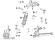
2009 Dodge Viper Shock Absorber Part Number: 5181425AB
$1202.25 MSRP: $1410.00You Save: $207.75 (15%)Ships in 1-2 Business DaysProduct Specifications- Other Name: Absorber - Suspension; Shock; Shock Absorber Suspension
- Item Weight: 5.40 Pounds
- Item Dimensions: 22.1 x 6.1 x 4.6 inches
- Condition: New
- Fitment Type: Direct Replacement
- SKU: 5181425AB
- Warranty: This genuine part is guaranteed by Mopar's factory warranty.

2009 Dodge Viper Shock Absorber, Front Part Number: 5181789AC
$358.39 MSRP: $528.00You Save: $169.61 (33%)Ships in 1-2 Business DaysProduct Specifications- Other Name: Shock - Front Suspension; Shock Absorber, Front; Coil Springs; Coil Spring; Spring; Shock; Spring And Shock Assembly Front Suspension
- Position: Front
- Replaces: 5181439AA, 5181787AC, 5181439AC
- Item Weight: 11.40 Pounds
- Item Dimensions: 22.6 x 6.0 x 4.5 inches
- Condition: New
- Fitment Type: Direct Replacement
- SKU: 5181789AC
- Warranty: This genuine part is guaranteed by Mopar's factory warranty.


2009 Dodge Viper Shock Absorber, Rear Part Number: 5181790AD
$357.07 MSRP: $801.00You Save: $443.93 (56%)Ships in 1-2 Business DaysProduct Specifications- Other Name: Shock - Rear Suspension; Shock Absorber, Rear; Coil Spring, Rear; Coil Springs; Coil Spring; Spring; Shock; Spring And Shock Assembly Rear Suspension
- Position: Rear
- Replaces: 5181788AC, 5181790AC
- Item Weight: 15.30 Pounds
- Item Dimensions: 29.0 x 6.3 x 5.2 inches
- Condition: New
- Fitment Type: Direct Replacement
- SKU: 5181790AD
- Warranty: This genuine part is guaranteed by Mopar's factory warranty.

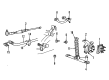
2009 Dodge Viper Shock Absorber, Rear Part Number: 5181434AC
Product Specifications- Other Name: Absorber - Suspension; Shock Absorber, Rear; Shock
- Position: Rear
- Replaces: 5181434AA, 5290040AE
- Condition: New
- Fitment Type: Direct Replacement
- SKU: 5181434AC
- Warranty: This genuine part is guaranteed by Mopar's factory warranty.
2009 Dodge Viper Shock Absorber, Front Part Number: 5181432AC
Product Specifications- Other Name: Absorber - Suspension; Shock Absorber, Front; Shock
- Position: Front
- Replaces: 5181432AA, 5290038AC
- Condition: New
- Fitment Type: Direct Replacement
- SKU: 5181432AC
- Warranty: This genuine part is guaranteed by Mopar's factory warranty.
2009 Dodge Viper Shock Absorber Parts and Q&A
- Q: How to Remove and Replace the Rear Coil-Over Shock Absorber on a Roadster on 2009 Dodge Viper?A: Before anything else, put the shock assembly into the mounting area and guide the clevis bracket end of the shock into the wheelhouse through the upper control arm and into the gap between the lower control arm and frame. Move the upper eye of the shock backward enough that the end of the clevis bracket moves over the isolator bushing on the lower control arm and settles onto the bushing and then bring the clevis bracket down so its upper eye is in the frame's hole. Attach the bolt and nut to the frame bracket and top of the shock assembly, but leave them just a smidgen loose for now and fasten the clevis bracket to the lower control arm isolator in the same way. Attach the tire and wheel assembly to the hub, tighten the nuts on the wheel mount to 135 Nm (100 ft. lbs.) in order and bring the vehicle down again. Once you've raised the top stack carpet, secure the shock service plug, lower the convertible top cover and then attach tack strips over the studs to secure the carpet. Nut-down the tack strips until the torque reaches 12 Nm (9 ft. lbs.), then put the rear window defroster electrical connectors in place. If required, apply butyl patches to the support panel of the folding cover to bind the tub, then shut and fix the top, checking its fit. Don't forget to fill the fuel tank as low levels will make the car seem shorter and also take out anything that's not part of what the car was built with from the cargo space. Always place the vehicle on a rack with turning plates at the front and slip plates at the rear and confirm that no tire is under or overinflated. Take the belly pan off the frame, lift up the rear of the vehicle and remove both the rear wheels and tires. Attach Suspension Height Stands, Special Tool 9096, to the vehicle where the wheels were and tighten all wheel mounting nuts to 135 Nm (100 ft. lbs.). Drop the vehicle and make sure you have removed the rear slip plate pins before you touch the Height Stands. Once the vehicle is at design height, make sure the orange plastic locating pins are put into their respective wheel hole in each Height Stand, where the front wheels slide into the 18 in. hole and the rear wheels into the 19 in. holes. The ends of Suspension Height Gages, Special Tool 6914, should be placed along the locating pins present in the ends of the Suspension Height Stands. Fit the Suspension Height Gage between the Stands and place it on the locating pins for correct alignment. Secure 150 pounds of weight in each cushion, for a total of 300 pounds, to reach the right design height; jounce the vehicle a few times and stop pushing at the bottom of the jouncing. Set the top of the Suspension Height Gage onto the surface and notice the difference in readings between it and every frame rail at the front edge of the Body Mount Gage. If you find the height is more than allowed, jounce the vehicle and measure it again, remembering to jounce before measuring. Before tightening, check where and how securely the rubber bushings are positioned, loosen them somewhat if they interfere with lowering the suspension, then adjust to the correct torque once it's reached the proper height. Tighten the two aforementioned bolts to 136 Nm (100 ft. lbs.), drive the car on level ground so it is at curb height and fit the rear wheelhouse splash shield in place. When finished, remove the special tools, lift the rear of the vehicle to Installed Position, install the wheel and tire set and torque the mounting bolts to 135 Nm (100 ft. lbs.) before lowering the vehicle.
Related 2009 Dodge Viper Parts
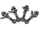 2009 Dodge Viper Alignment Bolt
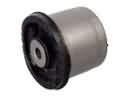 2009 Dodge Viper Axle Beam Mount
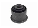 2009 Dodge Viper Axle Pivot Bushing
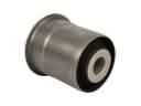 2009 Dodge Viper Axle Support Bushings
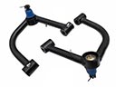 2009 Dodge Viper Control Arm
 2009 Dodge Viper Control Arm Bushing
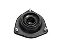 2009 Dodge Viper Shock And Strut Mount
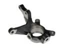 2009 Dodge Viper Steering Knuckle
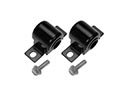 2009 Dodge Viper Sway Bar Bushing
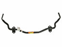 2009 Dodge Viper Sway Bar Kit
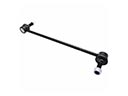 2009 Dodge Viper Sway Bar Link
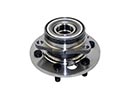 2009 Dodge Viper Wheel Hub