JeepParts
My Garage
My Account
Cart
OEM Chrysler Aspen Rod Bearing
Engine Connecting Rod Bearing- Select Vehicle by Model
- Select Vehicle by VIN
Select Vehicle by Model
orMake
Model
Year
Select Vehicle by VIN
For the most accurate results, select vehicle by your VIN (Vehicle Identification Number).
2 Rod Bearings found


Chrysler Aspen Bearings Part Number: 5012363AE
$16.87 MSRP: $25.00You Save: $8.13 (33%)Ships in 1-2 Business Days


Chrysler Aspen Connecting Rod Bearing Part Number: 68207790AA
$6.32 MSRP: $7.70You Save: $1.38 (18%)
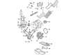
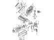
Chrysler Aspen Rod Bearing
Choose OEM Rod Bearing that meet Chrysler factory standards. Chrysler designs and tests every component for precision and durability. Each Rod Bearing follows strict manufacturing steps to lock in quality and fit. If your Chrysler Aspen matters to you, OEM parts make the smart choice. You'll get the exact look, feel, and performance you expect. Shop genuine Aspen parts at the highly competitive prices online. Enjoy a manufacturer's warranty, a hassle-free return policy, and rapid delivery. No more guesswork with off brands. Get genuine parts with exact fit and true factory performance. Shop with confidence today at JeepPartsDeal.com.
The Chrysler Aspen Rod Bearing is a crucial element that makes a seemingly huge difference for the Chrysler Aspen automobiles. Established to take the place of the crankshaft and the connecting rods, the Rod Bearing maintains the required smoothness in the rotation of the bearings together with low friction that is mandatory for important engine performance. Chrysler provides the buyers with bi-metal and tri-metal Rod Bearing and the latter features higher strength and fatigue resistance required for high-revving engines. The cylinder block of the E39 is produced through precision machining which enables the use of these Rod Bearings in a manner that ensures tight oil clearance that is very vital for performance. These advanced Rod Bearings are incorporated in the Chrysler Aspen, a car with luxury and a spacious interior that is made secure and efficient by the enhancement of its parts. Affordability along with compatibility with many other Aspen models guarantees that many drivers will be able to take advantage of the offered high-quality Rod Bearings. First of all, the Chrysler Aspen HEV is the hybrid model that reports the highest fuel consumption; it also demonstrates the significance of the Rod Bearing in improving performance without neglecting the environmental aspect. Some of the unique features are Dry Film Coatings for the Rod Bearings and modularity in eccentricity for resistance in extreme conditions for auto mobile Industries to get more durability and lubrication. In sum, the Chrysler Aspen Rod Bearing is dependable and powerful; the car model cannot be complete without it.
Chrysler Aspen Rod Bearing Parts and Q&A
- Q: What Are the Best Practices for Inspecting and Installing Rod Bearings on Chrysler Aspen?A:Check the connecting rod bearings for signs of these issues, scoring, typical wear, grooves, fatigue, and pitting, and take out any bearing that doesn't seem right. Be sure to check for wear, nicks, and burrs on the connecting rod journals, because badly aligned or bent rods may cause the Pistons, piston rings, cylinder walls, connecting rod bearings, and the crankshaft connecting rod journals to wear out quickly. Should the alignment cause the engine to wear unevenly or become damaged, look for any rod misalignment and fix any bent or twisted rods. Wipe the oil from the connecting rod journal, put a drop of oil on the upper bearing insert (2), and install the insert in connecting rod (1) so that it sits in the middle. The oil slinger pockets in the rods should face the front, and the "F"'s on the piston should point forward when piston ring compressor (3) and Guide Pins Special Tool 8507 (4) are used. Attach the lower bearing insert to the bearing cap, centering it, and confirm it is dry. Set Plastigage along the full width of the lower insert, in the middle, so it doesn't collapse; if the strip is crumbly, get yourself new Plastigage. After aligning the bearing cap and connecting rod with the journal, fasten the bolts to 27 Nm (20 ft. lbs.), but remove them again since the Plastigage will be smeared if you turn the crank. After removing the bearing cap, examine the size of the compressed Plastigage (2) to discover the clearance between the bearing and the journal. Keep in mind that the Engine Specifications give the proper clearance for easy reference. If the clearance is the same across all parts of the insert, it's probably normal. If it changes, check for signs of a tapered journal, a bent connecting rod, or trapped debris in the spaces. If the recommended clearance is available, just continue with installation, removing Plastigage (2) after installing the bearing inserts. If the clearance between the bearing and journal is greater than allowed, decide on which service bearing set is suitable. All connecting rod bolts are designed to break at their limits and can't be used again. Make sure to install new bolts each time you remove them. Additional Plastigage tests should be done before final assembly to confirm your bearing choice. Choose the proper insert, insert it, add the cap, and tighten the connecting rod bolts to 27 Nm (20 ft. lbs.) plus a 90° turn. Place a snug-fitting feeler gauge between the connecting rod and crankshaft journal flange, comparing it to the clearance specified in the engine manual, and change the connecting rod if it is out of specification.

Related Chrysler Aspen Parts
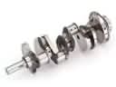 Chrysler Aspen Crankshaft
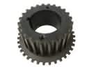 Chrysler Aspen Crankshaft Gear
 Chrysler Aspen Crankshaft Seal
 Chrysler Aspen Crankshaft Thrust Washer
 Chrysler Aspen Crankshaft Timing Gear
 Chrysler Aspen Cylinder Head Gasket
 Chrysler Aspen Pushrod
 Chrysler Aspen Rocker Arm
 Chrysler Aspen Timing Chain Tensioner
 Chrysler Aspen Timing Cover Gasket
 Chrysler Aspen Valve Cover Gasket
 Chrysler Aspen Valve Stem Seal