JeepParts
My Garage
My Account
Cart
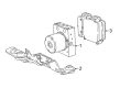
OEM Chrysler Voyager ABS Control Module
Anti Lock Brake Control Module- Select Vehicle by Model
- Select Vehicle by VIN
Select Vehicle by Model
orMake
Model
Year
Select Vehicle by VIN
For the most accurate results, select vehicle by your VIN (Vehicle Identification Number).
18 ABS Control Modules found

Chrysler Voyager Control Module Part Number: 68488633AA
$467.57 MSRP: $1055.00You Save: $587.43 (56%)Ships in 1-2 Business Days
Chrysler Voyager Modulator Valve Part Number: 68488632AA
$483.68 MSRP: $871.00You Save: $387.32 (45%)Chrysler Voyager Control Module Part Number: 68414159AB
$847.54 MSRP: $1300.00You Save: $452.46 (35%)Ships in 1-2 Business DaysChrysler Voyager Control Module Part Number: 68414163AB
$370.18 MSRP: $559.00You Save: $188.82 (34%)Ships in 1-2 Business DaysChrysler Voyager Control Module Part Number: 68414162AB
$370.18 MSRP: $559.00You Save: $188.82 (34%)Ships in 1-2 Business DaysChrysler Voyager Module - Anti-Lock Brake System Part Number: 68595269AB
$408.85 MSRP: $617.00You Save: $208.15 (34%)Ships in 1-2 Business DaysChrysler Voyager Control - Anti-Lock Brake Part Number: 68595268AB
$523.77 MSRP: $790.00You Save: $266.23 (34%)Chrysler Voyager Module - Anti-Lock Brake System Part Number: 68595270AB
$530.40 MSRP: $800.00You Save: $269.60 (34%)Ships in 1-2 Business Days
Chrysler Voyager Control - Anti-Lock Brake System Part Number: 68721993AA
$308.30 MSRP: $465.00You Save: $156.70 (34%)Ships in 1-2 Business Days


Chrysler Voyager Modulator Valve Part Number: 5018252AA


Chrysler Voyager Control Module Part Number: 5013865AB
Chrysler Voyager Control - Anti-Lock Brake Part Number: 68595267AB
$509.53 MSRP: $742.00You Save: $232.47 (32%)Chrysler Voyager Modulator Valve Part Number: 68414164AB
$966.38 MSRP: $1420.00You Save: $453.62 (32%)Chrysler Voyager Modulator Valve Part Number: 5018253AA

Chrysler Voyager Modulator Valve Part Number: 4882646
Chrysler Voyager Control Module Part Number: 5013864AB

Chrysler Voyager Control Module Part Number: 5093986AA
Chrysler Voyager Control Module Part Number: 5093988AA
Chrysler Voyager ABS Control Module
Choose OEM ABS Control Module that meet Chrysler factory standards. Chrysler designs and tests every component for precision and durability. Each ABS Control Module follows strict manufacturing steps to lock in quality and fit. If your Chrysler Voyager matters to you, OEM parts make the smart choice. You'll get the exact look, feel, and performance you expect. Shop genuine Voyager parts at the highly competitive prices online. Enjoy a manufacturer's warranty, a hassle-free return policy, and rapid delivery. No more guesswork with off brands. Get genuine parts with exact fit and true factory performance. Shop with confidence today at JeepPartsDeal.com.
Chrysler Voyager ABS Control Module plays an important role in the anti-lock braking of the car and is considered to be one of the most reliable and efficient across all the series of Chrysler Voyager. This module has the very important responsibility of preventing the locked wheel situation during the hard braking and to minimize the chances of skidding. The ABS Control Module works hand in hand with speed sensors, valves, a pump, and an ECU in order to provide the prime brake pressure control. In recent years, ABS Control Module also enclose features including the electronic stability control/ traction control, which enhances the car's steadiness by differentially commanding the wheels. This capability becomes more important for the Chrysler Voyager, since efficient and safety creates a positive image in auto-market offer. Chrysler Voyager ABS Control Module can support several types, and this guarantees that the drivers will experience the effectiveness of this equipment in any Voyager they use. The Chrysler Voyager is a successful model with its lifetime sales exceeding 12 million units and its ABS Control Module is the evidence of Chrysler's dedication to provide clients with only the prime products. Combining these options, Chrysler Voyager ABS Control Module also improves the car's performance during operation and increases the level of security in the process, which means that this component has a great demand among the Chrysler cars.
Chrysler Voyager ABS Control Module Parts and Q&A
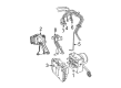
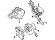
- Q: How to Service and Repair an ABS Control Module in a Left-Hand Drive on Chrysler Voyager?A:The first step to access the Hydraulic Control Assembly is to disconnect the negative battery cable, isolate it, remove the battery shield and pull the battery out. Take out the vacuum hose connector at the tank in the Battery Tray, then turn a screw to free the engine coolant filler neck from the battery tray and finally, take out the battery tray. Lock the brake pedal beyond the first inch using a brake pedal depressor to stop brake fluid from running out of the master cylinder after uninstalling the brake tubes from the HCU. Don't use a 12-volt power source on any terminals of the CAB connector if the 24-way connector is separated from the cable. Take away the wiring harness from the speed control servo, take out the mounting nuts and place the servo somewhere safe. Pulling the lock on the 24-way connector up will unlock it from the CAB. Soak all surfaces on the ICU and nuts for the brake tubes in Mopar Brake Parts Cleaner to make sure there is no dirt in the HCU system. Take out the four brake tubes from the outlet ports and pull both the primary and secondary brake tubes from the inlet ports on the HCU. Support the steering wheel and then take out the pinch bolt to split apart the steering shaft from the steering wheel. Should your car have clips, remove them from the silencer attached to the dash seal and then unscrew the three screws holding the dash seal in place. Take out the three bolts holding the ICU to the bracket and pull the unit through the engine compartment. Mount the ICU under the master cylinder in its bracket and secure the upper bolt for the first step. With the parts inside, attach the second set of mounting bolts and tighten all three to 11 Nm (97 in. lbs.). Attach the dash seal and its screws again and if the truck is so equipped, the silencer too. Attach the steering shaft coupling and tighten the pinch bolt to a force of 28 Nm or 250 in. lbs. Do not place the primary and secondary brake tubes next to one another or against other components when installing the system. Connect the brake tubes to the ports on the HCU assembly and then tighten the nuts on them to 17 Nm (145 in. lbs.). Place the four brake tubes into their proper spots on the HCU valve block, then hand torque them to 17 Nm (145 in. lbs.). The seal in the CAB should be fitted correctly before you fit the 2-way connector. Set the 24-way connector inside the CAB socket, then push it down and secure it. Add routing clips to the brake tubes, take off the brake pedal holder and fit the speed control servo onto its mounting bracket. Engage the speed control servo wiring, assemble the battery tray and re-install its screw. Attach the vacuum hose connector, put in the battery and battery shield and reconnect the negative cable to the battery. After that, completely drain the Base and ABS brake hydraulic lines and test the vehicle on the road to be sure it is safe.
- Q: How to Remove and Install an ABS Control Module in a Left-Hand Drive on Chrysler Voyager?A:Turn off the negative cable of the battery, separate it from the car and isolate it and then remove the shield and battery. Dislodge the vacuum hose connector at the tank built into the Battery Tray, remove the screw holding the engine coolant to the battery tray and remove the battery tray. Press the brake pedal down at least one inch with a brake pedal depressor to keep the brake fluid from being drained out of the master cylinder when removing the brake tubes from the HCU. Don't attach a 12-volt power supply to the CAB connector when it's unplugged. Cut the speed control wires, hang the servo aside and take out the nuts holding the servo in place. Remove the 24-way connector from the CAB by pressing up on the lock to release it. Use Mopar Brake Parts Cleaner to wipe down all the ICU and tube nut surfaces, before removing the brake tubes from the HCU's inlet and outlet ports. Securely center the Steering Wheel, remove the panel located underneath the instrument panel, free the steering shaft coupling pin bolt and unfasten both the clips and screws that hold the silencer to the dash seal. Unscrew the bolts that join it to the bracket and bring the ICU down through the engine bay. Set the ICU into its bracket beneath the master cylinder and then start installing the upper mounting bolt. Within the vehicle, fit the final two bolts into the bracket and tighten all three to 11 Nm (97 in. lbs.). Install the dash seal and three screws, followed by the silencer above the seal. Bring together the steering shaft coupling, fit the pinch bolt in place, then clamp it tight with 28 Nm (250 in. lbs.) force. Slip the silencer panel onto the steering column again, remove the braking pedal holder and be sure all tubes are set up in the correct direction so they do not make contact with the other components. Fit the main and secondary brake tubes into the HCU valve block at the right connections and tighten the tube nuts to 17 Nm (145 in. lbs.). Attach the four chassis brake pipes to where they belong on the HCU valve block and tighten each of their nuts to 17 Nm (145 in. lbs.). After putting the seal in the main connector, insert it into the Comms Avionics Bay socket and push it down to the bottom while locking it into position. Add any special routing clips to the brake tubes, take off the brake pedal holder, set up the speed control servo with its nuts and attach the wiring harness again. Place the battery tray back, attach the coolant filler neck screw, join the vacuum hose once more, put the battery and its cover into place, reattach the negative cable, drain and top off the two brake hydraulic systems and drive the car briefly to ensure both systems are working smoothly.


Related Chrysler Voyager Parts
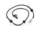 Chrysler Voyager ABS Sensor
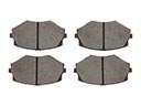 Chrysler Voyager Brake Pads
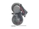 Chrysler Voyager ABS Pump And Motor Assembly
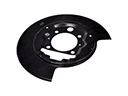 Chrysler Voyager Backing Plate
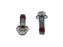 Chrysler Voyager Brake Caliper Bolt
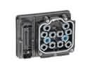 Chrysler Voyager Brake Controller
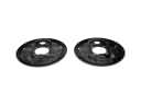 Chrysler Voyager Brake Dust Shields
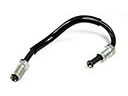 Chrysler Voyager Brake Line
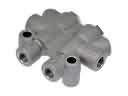 Chrysler Voyager Brake Proportioning Valve
 Chrysler Voyager Brake Rotor
 Chrysler Voyager Hydraulic Hose
 Chrysler Voyager Wheel Hub Bolt