JeepParts
My Garage
My Account
Cart
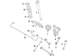
OEM Dodge Magnum Sway Bar Kit
Stabilizer Sway Bar Set- Select Vehicle by Model
- Select Vehicle by VIN
Select Vehicle by Model
orMake
Model
Year
Select Vehicle by VIN
For the most accurate results, select vehicle by your VIN (Vehicle Identification Number).
7 Sway Bar Kits found


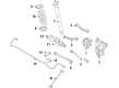
Dodge Magnum Stabilizer Bar, Rear Part Number: 4782873AB
$104.21 MSRP: $154.00You Save: $49.79 (33%)Ships in 1-2 Business Days
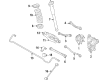
Dodge Magnum Stabilizer Bar, Rear Part Number: 4782871AB
$60.84 MSRP: $89.50You Save: $28.66 (33%)Ships in 1-3 Business Days


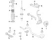
Dodge Magnum Stabilizer Bar, Front Part Number: 4782544AC

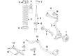
Dodge Magnum Stabilizer Bar, Front Part Number: 4782541AC

Dodge Magnum Stabilizer Bar, Rear Part Number: 4782872AB
Dodge Magnum Stabilizer Bar, Front Part Number: 4782543AC

Dodge Magnum Stabilizer Bar, Front Part Number: 4782950AB
Dodge Magnum Sway Bar Kit
Choose OEM Sway Bar Kit that meet Dodge factory standards. Dodge designs and tests every component for precision and durability. Each Sway Bar Kit follows strict manufacturing steps to lock in quality and fit. If your Dodge Magnum matters to you, OEM parts make the smart choice. You'll get the exact look, feel, and performance you expect. Shop genuine Magnum parts at the highly competitive prices online. Enjoy a manufacturer's warranty, a hassle-free return policy, and rapid delivery. No more guesswork with off brands. Get genuine parts with exact fit and true factory performance. Shop with confidence today at JeepPartsDeal.com.
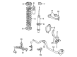
As with all cars, handling is an issue, however, the Sway Bar Kit for Dodge Magnum cars connects both sides of the suspension. This connection also having a role in decreasing body roll during aggressive cornering and rough surfaces stability increases as well. The anti-roll bar works based on the torsion capacity; this makes the wheels always at equal heights thus reduces side to side angle and increases ground friction. Adjustable and active anti-roll bar styles of Sway Bar Kits have been used in Dodge Magnum in different years of production. These more complex systems may be made to be variable, where they adjust the stiffness to improve the handling ability and comfort of the ride. Although they enhance the handling of the automobile, standard sway bars deliver some of the shocks between the wheels creating a 'waddling' on the uneven surface. All in all, Dodge Magnum Sway Bar Kit is one of the most important components that affect the car's handling balance and consequently its behavior on the road.
Dodge Magnum Sway Bar Kit Parts and Q&A
- Q: How to Service and Repair a Rear-Wheel Drive Sway Bar Kit on Dodge Magnum?A:Before you can service or repair the rear-wheel drive vehicle's sway bar kit, raise the car and remove the belly pan. Enter the hatch and on each side, remove the screws holding the sway bar kit heat shield in place and pull out the heat shield. Unscrew the bolts that hold the sway bar kit isolator retainer on each side, then remove both halves of the retainers from all around the sway bar kit isolator. Unplug the slit to clear off every isolator from the sway bar kit. Then, take the nut joining the sway bar link to the bar off from either side and slide the link ball joint stem away from the bar. When both sides are done, take the entire bar out of the vehicle. When installing, lift the sway bar kit to the sway bar link, slip the link ball joint stem into the hole in the bar and temporarily install the nut. Make sure you put on the sway bar kit isolators correctly; use the slit in each isolator and mount it against the locating collar on the rear end of the vehicle. Add each sway bar kit isolator retainer half around the isolator on each side, followed by securing them with bolts tightened to 60 Nm (44 ft. lbs.). Set the heat shield back on the sway bar kit and use screws to secure it to the isolator retainer. As you let the stem continue to rotate, fasten both of the sway bar link nuts at the ends of the bar till the torque reads 128 Nm (95 ft. lbs.). In the end, put the belly pan back on and apply weight to the wheels to bring the vehicle down after the install.
- Q: How to Install a Sway Bar Kit and Its Components on Dodge Magnum?A:Start by putting isolators on the sway bar kit, making sure that the slits in the bushings point forward and the flat part of the bushing is next to the crossmember. Then, secure retainers to the isolators and attach the whole bar with isolators and retainers on top of the crossmember. First, secure the isolator retainer mounting bolts temporarily, then secure the bolts and nuts that fasten the sway bar kit ends onto the sway bar links, also without tightening either. Turn the isolator retainer mounting bolts to tighten them to 61 Nm (45 ft. lbs.). Disconnect the Coil Springs with isolators from the spring links, lift the crossmember so it sits at the body mounting points and attach the propeller shaft to the rear axle differential. Remember that because the rear mount bolts can protrude into the frame, the rear ones should never be put at the front. Keep raising the crossmember until you can add the mounting bolts, but don't tighten the left side bolts just yet. Drop the jack enough that only the right side crossmember is a little lower than the car body so the spring and isolators on the right side of the car fit correctly. Attach the coil spring to the body mount spring pocket, place the coil spring between the Shock Absorber and the body and then lift the jack to slide the coil spring and lower end into place, stopping when the shock absorber mounting hole aligns with the spring link. Fit the lower shock mounting bolt and nut, but don't tighten them yet. On an AWD vehicle, put the spacers over the right crossmember mount bushings before you lift the crossmember. On the right side, place the crossmember correctly and insert the bolts, tightly enough so they aren't moving. With the bolt holes lowered, detach both the front and Rear Crossmembers from the far left side, then drop the jack from underneath the car to allow enough of the left crossmember to be lowered for spring installation, checking that all isolators are installed. Place the coil spring into the spring pocket, put it in line with the body mount, raise the jack until the lower end of the shock and shock's lower mount hole is level with the spring link and stop. Put in both the lower shock mounting bolt and nut, but don't tighten them yet. For any AWD vehicle, add spacers to the left crossmember mount bushings before you raise the crossmember. Plug the left side of the crossmember into place and insert the bolts from beneath the frame, hand-tightening them only for now. Move the crossmember as needed so that the mounts match the marks on the body, then make sure the distance from the tension link to the weld flange on the body is greater than 12 mm for good suspension movement. When the gap is smaller than 12 mm, move that part of the rear crossmember back until it's correct, add the bolts up and recheck the other side. Turn each of the crossmember bolts to 180 Nm (133 ft. lbs.) and remove both the jack and the bungee from the differential and propeller shaft. Correctly position the propeller shaft index marks, put on the rear coupler-to-axle bolts and nuts by hand and then use a wrench to tighten each to 81 Nm (60 ft. lbs.). Slide in the fuel filler tube, clip the left rear wheel speed sensor cable to the routing clip by the body connector and attach the left rear wheel speed sensor connector to the right sensor connector. Snap both ends of the speed sensor connectors into the body wiring harness connector beneath the luggage compartment. Caliper guide pin bolts should be screwed in after cleaning the threads and using Mopar(R) Lock & Seal Adhesive or an equivalent alternative. To fit standard or premium disc brakes, stick the caliper guide pins into the caliper adapter, draw the caliper and brake hose up through the rear suspension, put the caliper on the Brake Pads, align the holes on the guide pins with those on the adapter and secure the guide pin bolts with 31 Nm (23 ft. lbs.) of torque, keeping the guide pins from turning as you tighten the bolts. Check that the brake hose is held by metal support clips and goes forward from the brake valve. To install SRT8 disc brakes, put the spring link onto a transmission jack, push the caliper, along with the pads, over the brake rotor, point the caliper at the knuckle and fasten the caliper mounting bolts to 130 Nm (96 ft. lbs.). With the jack out from beneath the spring link, attach the Parking Brake Cable bracket locating pin to the front flange of the crossmember and then screw the cable routing bracket to the rear crossmember. Put the parking brake cable above the rear crossmember and lead it up through the equalizer above the rear axle differential. Bridge the front parking brake cable to the connector on the right rear cable. Put on the rear exhaust system, then install the tires and wheels, tightening the wheel-mounting nuts to 150 Nm (110 ft. lbs.) or 190 Nm (140 ft. lbs.) according to the requirement for police cars. Set the rear wheels so that they slightly rise above the floor level when the car touches down, engage the parking brake lever, let go and then engage again to confirm the wheels don't turn. After lowering the car, fix the negative cable of the battery to the battery post and swiftly pump on the brake several times until the pedal stops bouncing. Skid the vehicle onto an alignment rack or drive-on hoist, raise the vehicle to reach the mounting nuts, fasten the shock absorber bolts to 72 Nm (53 ft. lbs.) and tighten the sway bar kit link fasteners to 61 Nm (45 ft. lbs.). Later, align the wheels and focus on the thrust angle. In case the thrust angle must be corrected by shifting the rear crossmember, check that the tension link clearance is adequate.


Related Dodge Magnum Parts
 Dodge Magnum Control Arm Bushing
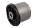 Dodge Magnum Axle Beam Mount
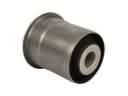 Dodge Magnum Axle Support Bushings
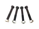 Dodge Magnum Control Arm Bolt
 Dodge Magnum Lateral Link
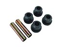 Dodge Magnum Leaf Spring Bushing
 Dodge Magnum Shock Absorber
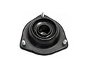 Dodge Magnum Shock And Strut Mount
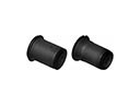
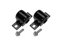 Dodge Magnum Sway Bar Bushing
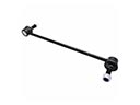 Dodge Magnum Sway Bar Link
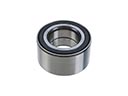 Dodge Magnum Wheel Bearing
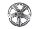 Dodge Magnum Wheel Cover