JeepParts
My Garage
My Account
Cart
OEM Dodge Stratus Wheel Bearing
Hub Bearing- Select Vehicle by Model
- Select Vehicle by VIN
Select Vehicle by Model
orMake
Model
Year
Select Vehicle by VIN
For the most accurate results, select vehicle by your VIN (Vehicle Identification Number).
4 Wheel Bearings found


Dodge Stratus Hub & Bearing, Front Part Number: 4578144AB
$248.54 MSRP: $318.00You Save: $69.46 (22%)Ships in 1-2 Business Days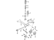
Dodge Stratus Hub & Bearing Part Number: 4616263AA
$19.82 MSRP: $114.00You Save: $94.18 (83%)Ships in 1-2 Business Days
Dodge Stratus Hub & Bearing, Front Part Number: MR334386
$149.65 MSRP: $212.00You Save: $62.35 (30%)Ships in 1-2 Business Days
Dodge Stratus Hub Assembly, Rear Part Number: MB892408
Dodge Stratus Wheel Bearing
Choose OEM Wheel Bearing that meet Dodge factory standards. Dodge designs and tests every component for precision and durability. Each Wheel Bearing follows strict manufacturing steps to lock in quality and fit. If your Dodge Stratus matters to you, OEM parts make the smart choice. You'll get the exact look, feel, and performance you expect. Shop genuine Stratus parts at the highly competitive prices online. Enjoy a manufacturer's warranty, a hassle-free return policy, and rapid delivery. No more guesswork with off brands. Get genuine parts with exact fit and true factory performance. Shop with confidence today at JeepPartsDeal.com.
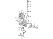
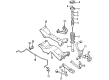
The Wheel Bearing is an important assembly part that goes along way in also increasing the efficiency and robustness of the Dodge Stratus which is a mid-size automobile manufactured from 1995 to 2005. Considered as a highly durable part, the Wheel Bearing enables the wheels of the Dodge Stratus to rotate without much effort while, at the same time, contribute greatly to the car's safety. Being available in three options of the hub and bearing arrangements, including the assembly to the unit with an ABS sensor, the Wheel Bearing can fit virtually any Stratus model, which is why it can be chosen as the car's equipping by many drivers. Imperfect Wheel Bearings may be loose or worn and this results in noise or vibration and or wheel loss hence the need for inspection and replacement. The type of bearings used in the powertrain of the Dodge Stratus are the replaceable tapered roller bearings and they need to be well greased for efficiency and adjustments. Also, resulting from the reduction of friction, the Wheel Bearing contributes to better fuel economy, which the Dodge Stratus gains an average of 20-21 /city and 26-29 /highway. With such performance and safety characteristics, the Wheel Bearing is highly demanded in the automotive industry so that drivers could receive real pleasure from driving. In general, the Wheel Bearing is vital in ensuring the structural and operational aspects of the Dodge Stratus and it is therefore among the parts that every owner should consider as vital in order to improve his car.
Dodge Stratus Wheel Bearing Parts and Q&A
- Q: How to Service and Repair a Front Wheel Bearing on Dodge Stratus?A:Before handling the front wheel bearing, lift the vehicle, take off the front wheel and tire from the hub and ensure the hub nut is not loose, as this can cause wheel bearing harm once the car is off the ground. Place the brakes on, then loosen the hub nut, so you can remove the caliper, adapter, shoes and rotor from the Steering Knuckle. Hold the rod stud with a socket while loosening the nut on the outside of the steering knuckle. Afterward, remove the Tie Rod End with the Remover, Special Tool MB-991113. If the car comes equipped with antilock brakes, remove the speed sensor cable bracket out of the steering knuckle. After that, remove the cotter pin and castle nut from the lower Ball Joint stud, making sure not to put any tool between the steering knuckle and the joint. Turn the steering knuckle to the side and strike the boss on the steering knuckle with a hammer to split it from the lower ball joint stud, making sure you do not damage the lower Control Arm or the ball joint grease seal. Raise the steering knuckle to remove it from the stud below the lower ball joint. Make sure not to damage the ball joint seal or split the CV joint inside. As you pull the steering knuckle away, support the driveshaft and then free the upper ball joint stud using the cotter pin and nut. With the Puller, Special Tool C3894-A, withdraw the upper ball joint stud from the steering knuckle after removing the cotter pin and nut. Get rid of the steering knuckle from the car and secure it in a vise, then unbolt the hub and bearing assembly. Pull out the assembly with a hammer if it's stuck. Wipe all the surface areas where the steering knuckle mounts, replace the hub and bearing assembly, line up the bolt holes and fasten the three screws to a torque of 110 Nm (80 ft. lbs.). Table of contents Put the upper ball joint stud into the steering knuckle and hold it there with the castle nut, turning both the upper and lower ball joint castle nuts to 74 Nm (56 ft. lbs.) and 62 Nm (45 ft. lbs.) with the torque wrench. If the bike comes with antilock brakes, mount the speed sensor by means of the mounting bracket and then secure it with the attaching bolt. Before connecting the tie rod end to the steering knuckle, put the heat shield in place, apply 61 Nm (45 ft. lbs.) of torque to the nut and keep the stud in place. Add the brakes and adapter assembly, seal the corners of the pads, fit the hub nut onto the driveshaft stub axle and clean the C/V joint stub axle threads before inserting the nut. After braking the vehicle and tightening the hub screw, put the wheel and tire back in place. Use 100 ft. lbs. of torque to tighten each lug nut in its correct position. After that, lower the vehicle and set the front toe to meet the required specifications.
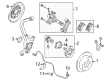
- Q: How to Install a Wheel Bearing on the Knuckle Spindle on Dodge Stratus?A:Install the hub and bearing sections onto the knuckle spindle by putting a NEW retaining nut in place and tightly securing it to 250 Nm (185 ft lb.). Then, use a soft faced hammer to install the hub and dust cap bearing. When that is the case, place the brake rotor and caliper on the vehicle. For those with rear drums, remember to install the drum and correct the brake shoes when required. Set up the rear tire and wheel assembly and gradually tighten all wheel stud nuts by intersecting your pattern to reach 135 Nm (100 ft. lbs.) of torque as you go. Afterward, lower the vehicle to the ground.


Related Dodge Stratus Parts
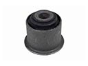 Dodge Stratus Axle Pivot Bushing
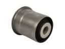 Dodge Stratus Axle Support Bushings
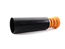 Dodge Stratus Bump Stop
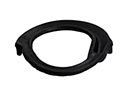 Dodge Stratus Coil Spring Insulator
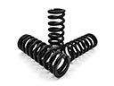 Dodge Stratus Coil Springs
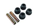 Dodge Stratus Leaf Spring Bushing
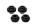 Dodge Stratus Radius Arm Bushing
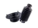 Dodge Stratus Shock and Strut Boot
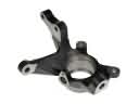 Dodge Stratus Steering Knuckle
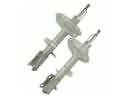 Dodge Stratus Strut Housing
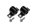 Dodge Stratus Sway Bar Bushing
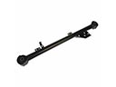 Dodge Stratus Trailing Arm